Marshall JCM 2000 Replacement PCB – TSL100 and DSL100 bias drift repair using the ROS-2000 board

Marshall JCM 2000 Replacement PCB

Marshall JCM 2000 – ROS-2000 board design overview

We’ve had a few questions about the ROS-2000 replacement board that I designed for the Marshall JCM 2000, so I thought it was worth putting a proper nerd level explanation together. Buckle up!

The project was a collaboration with Stewart at www.valvetubeguitaramps.com and it’s available exclusively from his website at the following link ROS-2000 PCB for JCM2000 Amplifiers – Valve Tube Guitar Amps

This isn’t a quick overview – it’s very much a “what we did and why” from a repair and design point of view. Buckle Up!

What the board is (and why it exists)

The ROS-2000 is a replacement for the original Marshall valve PCB, which is well known for a few issues – we mostly see them with the bias drift issue, in which a conductive board causes a thermal runaway, killing the EL34 valves.

The aim here wasn’t to reinvent the amp, just to fix the weaknesses properly and make something that’s reliable long-term.

Everything was designed here at Keld Ampworks in Nottinghamshire and manufactured in the UK, rather than partially outsourced and “finished” locally. Stewart at vtga spoke to a load of UK manufacturers to select the best for the job. In the end we settled on a manufacturer in Hastings, UK (1066!) to build the main part of the board and completed the configuration here in Keld Ampworks or at Stewart’s site on the beautiful North Yorkshire coast.

Component choices

Across the board, we’ve uprated pretty much everything:

  • Signal resistors are metal film (lower noise than carbon types)
  • High-voltage resistors are 2W rated for extra headroom
  • Film capacitors are Wima
  • Ceramics are Vishay / Murata
  • Electrolytics are Rubycon / Nichicon / Nippon Chemicon

Nothing exotic, just good-quality, proven parts with sensible ratings.

Whilst designing this board I noticed that there’s a capacitor in the original design that ends up reverse-biased in certain switching modes. That’s been corrected here, as it’s not something you want for long-term reliability, although I haven’t seen it cause failures!

Fixing the original fault (bias drift)

The big issue on these amps is leakage between high voltage (HT) and the bias supply.
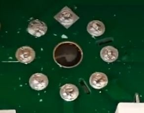
PCB slots to fix the bias drift issue on the Marshall JCM2000

That’s addressed in a few ways:

  • Physical slots cut into the PCB to increase isolation
  • Much greater spacing between HT and bias traces
  • Careful routing so the two don’t run even slightly close together

There’s also an external link used to route HT rather than crossing sensitive areas of the board.

Despite extensive design reviews we still had a nervous moment when we ran the board up for the first time, but the result was no measurable bias drift, even under quite severe heat stress testing.

Heat management

The original board uses a bridge rectifier for the heater supply, which runs hot.

That’s been replaced with four discrete diodes, spaced for airflow.
They run cooler and don’t dump heat into the PCB. This issue originally caused hum noises in the clean channel on the JCM 2000 boards.

Surface Mount Components

Surface-mount tends to get a bit of a bad reputation in valve amps, so it’s probably worth addressing that directly.

They’re not used here as a cost-saving exercise – in fact our choice to use surface mount actually added cost, as we had run 2 manufacturing passes rather than a single through-hole build.

The only reason they’re used is because, in those specific parts of the circuit, they’re simply the right choice and reducing the component footprint on the switching circuit allowed us more space elsewhere to eliminate cross talk and heat disipation issues.

All of the surface-mount components are in low-voltage areas, with nothing seeing more than around 10–12V and no meaningful heat being generated. In that context, they’re perfectly reliable and allow for a cleaner layout, particularly in keeping the ground plane intact, which helps keep noise down.

Where there’s high voltage or any real power dissipation, it’s all traditional through-hole parts as you’d expect.

So it’s not a blanket approach – just using each type of component where it actually makes sense. Engineering is about using the right part for the job, not dogmatically rejecting technology based on internet nonsense! Sorry guys!
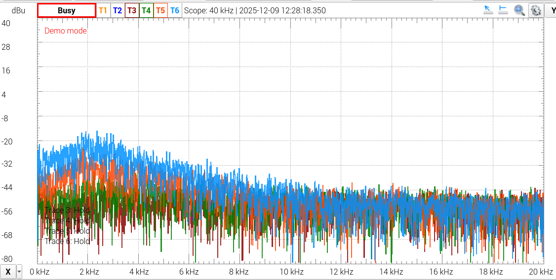
Reducing noise on a JCM2000 with the ROS-2000 PCB

Layout and grounding

Connector positions are kept similar to the original, so installation is straightforward and doesn’t require reworking wiring looms.

On the PCB itself:

  • Surface-mount parts are used only where appropriate (low voltage, no heat). We
  • Through-hole parts are used where needed for robustness
  • A full ground plane is used on the underside

There’s a lot of debate about ground planes in valve amps, but in practice, done properly, they reduce noise and interference – and that’s been borne out in testing. In my previous engineering career before Keld Ampworks I spent a substantial amount of time testing audio euqipment for harsh EMC environments. Ground planes reduced interference IN EVERY SINGLE CASE. That said, inexperienced PCB designers might make mistakes with running low impedance ground panes near radiated sources to cause problems. Fortunately, we avoided that and this unit is measurably quieter than other options as a result of sensible tracking and the ground plane.

The other common complaint about valve amps is that “LEO FENDER DIDN’T USE A GROUND PLANE”. Well Leo didn’t use his amps near wifi, or wireless rigs, or lighting rigs with SMPS sources. I’ve played on stages where ’boutique’ amps have been plagued with RF interference noise whilst my own ground plane amps have stayed beautifully quiet. It’s just good engineering, folks.

Mechanical reliability

A couple of small but important details:

  • Raised components use ceramic spacers, so they can’t bend and short during shipping
  • Components are secured with non-acetone silicone, not hot glue (which goes brittle with heat)

These are the kinds of things that don’t show up immediately, but matter over time.
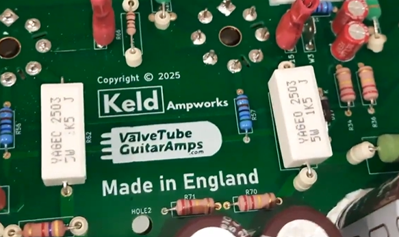
Uprated screen grids in the JCM2000 upgrade PCB

Other improvements

A few additional tweaks:

  • Screen grid resistors uprated to 1k5 to extend valve life
  • Flyback diodes added to protect the output transformer
  • Improved heater trace layout and balancing – see previous comments about understanding how to design PCBs with ground planes!

None of these change the sound in any way, but they do make the amp more robust and lower noise.

Testing

We tested the prototypes extensively to make sure that they matched up to the most recent (best) Issue 20 Marshall PCBs. The frequency responses matched up perfectly in all channels on our test TSL100 and our test DSL100. We tested it at every knob extreme and also tested the Tone shift, boost/mid boost deep and presece performance. The waveforms also matched up in clean and clipping performance. We then tested the noise and found that we had indeed managed to make the unit slightly quieter. Ground plane, folks.

Have you waded through all that? I’m impressed.

This isn’t about changing the character of the amp, it’s about making it behave properly.

The original design works, but it has some weak points. The ROS-2000 board addresses those with better layout, better parts, and a bit more attention to how things behave under real-world conditions (heat, vibration, long-term use).

Hope that was useful, if you like what you see, please do head on over to Stewart’s website here: ROS-2000 PCB for JCM2000 Amplifiers – Valve Tube Guitar Amps

If anything’s unclear or you’ve got specific questions about the design, feel free to ask.
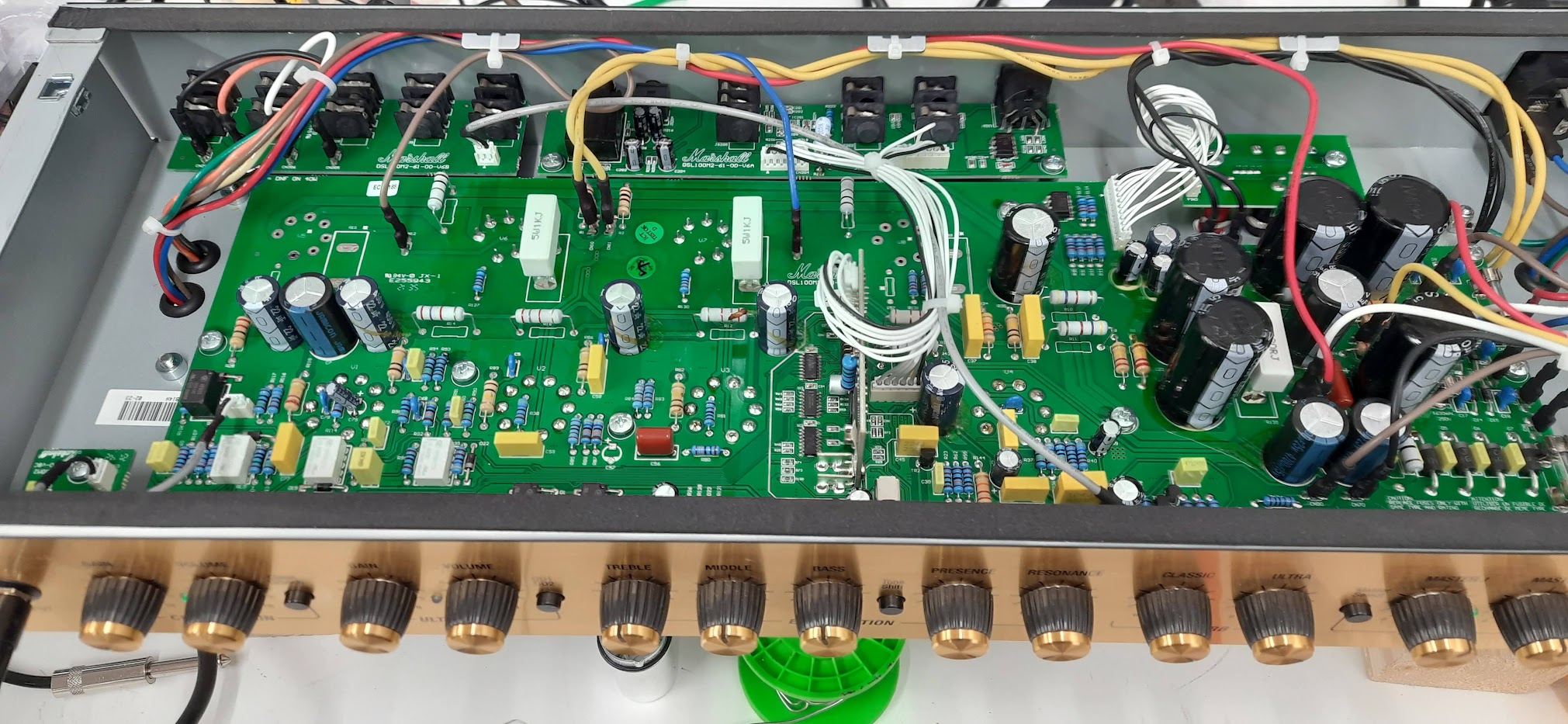
Marshall DSL40CR

DSL40CR repair

I don’t often see a DSL40CR come through with this kind of erratic behaviour – it was one of those jobs that kept me scratching my head until the real root cause showed itself.

The Symptoms (as described by the customer)

  • The amp would unpredictably switch from the Clean channel into Overdrive (OD) without touching the footswitch or front panel. I noticed that putting the amp in standby would instanly trigger the fault
  • Otherwise, it sounded fine: the valves were healthy, the output stage appeared to behave, and no obvious catastrophic faults were present.

Removing a valve changes the power supply behaviour, so that’s where I started.

What I found was subtle: the control supply (low voltage rail) was not rock solid. The rail that feeds the preamp switching logic and control electronics was sagging or shifting, just enough so that under certain conditions the amp would interpret it as a switch command.

Once the control rail wobbled or dipped, the channel logic would misbehave and flip the amp into OD mode. A surprising symptom, but less surprising once you realize how sensitive those digital / switching circuits can be when their supply is out of spec.

I’m lucky enough to have a friend who knows the technical issues with this range of amps better than literally everyone else in the world. He suggested I look at the power supply section on the rear board as this is the most prone to sagging.

In addition, during the inspection I noted a few design / build quirks that I’ve occasionally encountered in the DSL40CR family (and in other Marshall amps), which may be part of why these amps sometimes exhibit low output or noise issues:

  • Low power / reduced volume: I’ve seen DSL40CRs (and sibling models) drift into low power mode, often caused by conductive glue traces (flux residue or glue meant for mechanical stability) creeping between printed traces, forming parasitic leakage paths. These “hidden conductive paths” can robs bias or collapse gain subtly, especially under heat.
  • Noise issues from 1 M grid resistors: Some of those 1 M grid or grid‑stop resistors in the preamp are notorious for turning noisy over time, especially when they drift in value or have internal contamination. That adds hiss or crackle, especially on the quieter parts of the circuit.
  • Shorting via ceramic resistor bodies: I’ve even found situations where the body of a ceramic resistor is so close to a high voltage (HV) board trace that it arcs or shorts under certain conditions – e.g. if the resistor’s coating is cracked, or there’s flux residue, or simply vibration has shifted things. That can cause weird intermittent behaviour, grounding, or leakage between circuits.

So, while the main symptom in this unit was the channel‑switching, it was wise (and necessary) to check for all these known weak spots in the DSL40CR line.

After these repairs, the DSM40CR stayed rock solid in each channel: no more phantom switching. I ran the amp through its full range of channels, settings, footswitch tests, power cycling, and warm-up cycles. Then I subjected it to a soak test at gigging levels for a good hour or two – it remained stable, no drift, no switching anomalies.

I also measured output power and bias and compared it to spec – it was right in the expected ballpark (i.e. no low‑power symptoms). That confirmed that the power stages and bias were healthy.

If you have a DSL40CR (or any Marshall) behaving oddly – randomly jumping channels, volume sagging, noise creeping in – don’t assume the worst (i.e. bad valves). A disciplined service + power‑supply / control circuit check is often all that’s needed to bring it back to life. Please do get in touch

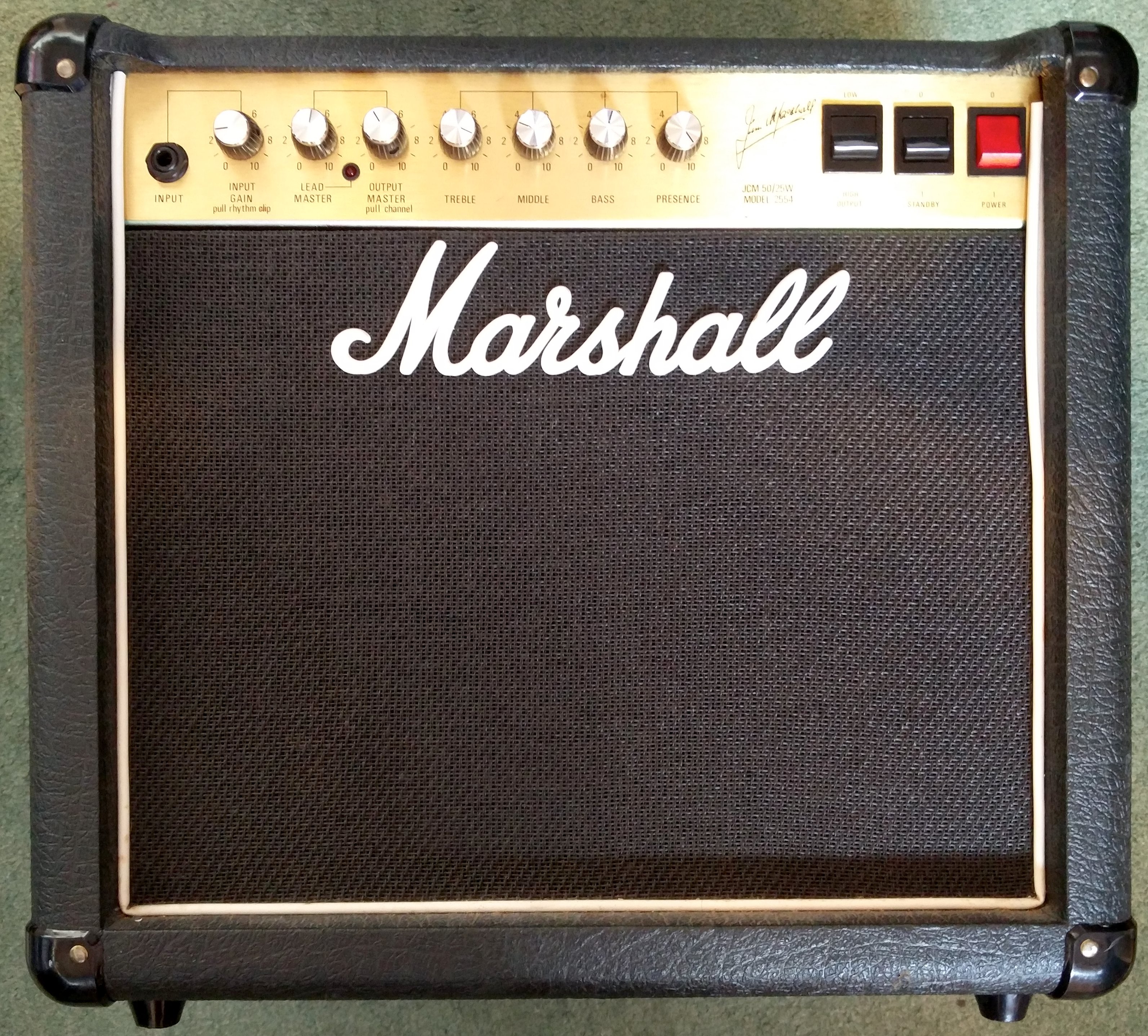
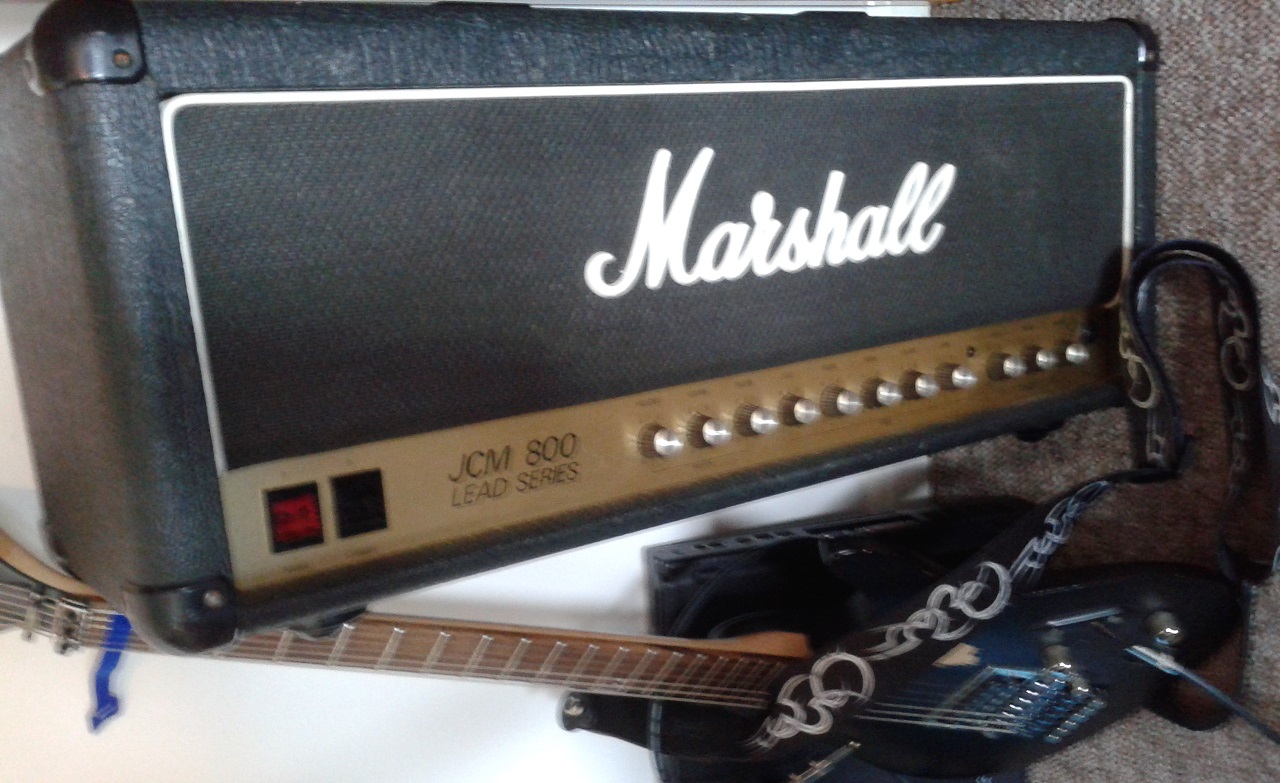
Marshall 2554 JCM 800 combo repair

Marshall 2554 JCM 800 combo repair-4

This JCM800 combo repair came to me for a full service before the user sold it. It also had a common problem with the power light illumination.

I spotted a few things during the service. A bit of preventative action has hopefully made the amp a more pleasurable experience for the user.
Replacement Marshall JCM800 Switch
There were a couple of dry joints around the potentiometers. All three preamp valves failed test.

The valve socket for the preamp valve was damaged and required replacement – I used a new Belton PT range socket, I find these to be durable and high quality with a good solid fixing. The first valve socket was

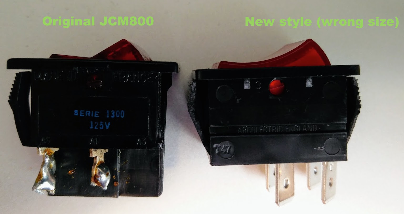
The illumination switch would have been a nice simple job, except that the part sold by Hot Rox as a “Marshall JCM800 power switch” was too wide for the chassis slot. Fortunately I found a suitable replacement from RS. That’s one to beware of in future!

The owner was good enough to write me a nice review of the service. 🙂

Replacing power switch Marshall 2554 JCM800 combo repair-1
If you need a JCM800 Combo repair please get in touch and I’ll get it sorted for you.

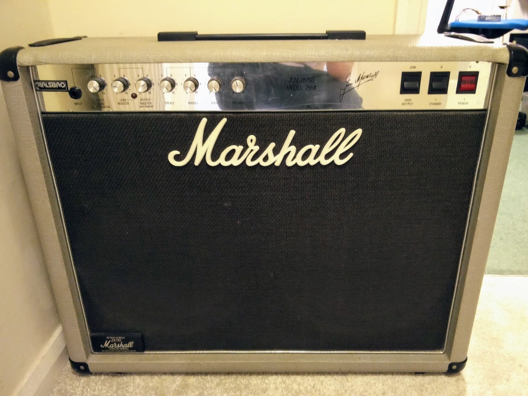
Marshall Silver Jubilee repair – Marshall model 2558

Marshall Silver Jubilee Repair

I was quite intruiged when a Nottingham guitarist brought this Marshall Silver Jubilee repair to my Newark workshop. These amps have taken on a bit of a legendary status, due in no small part to their association with Slash and Joe Bonamassa. I love how this amp looks, and it’s got an interesting tone control design, that deviates from the common Fender and Marshall designs.

The amp had blown a power tube, which the owner had replaced without rebiasing, tut tut! It still had very weak output, but occasionally it would blast out at full volume. It was also in need of a good pot clean.

First thing to do was to disassemble the amp. Marshall amps from this era are quite nice to work on and easy to take apart.
Marshall Silver Jubilee Repair - gutshot
The described problem was caused by oxidation in the FX loop circuit. This is a common problem with many amps and was easily fixed.

I observed some crackling on the EQ potentiometers which turned out to be slightly leaking coupling capacitors in the tonestack.

I then attempted to rebias the amp but discovered another problem. The plate voltage of 490V requires a bias current of to give 70% bias. I couldn’t get higher than 18mA with the valves the customer has fitted. Viewing the output waveforms in the scope, the amp showed significant crossover distortion. I checked the bias supply and found it to be working correctly. Although they tested within spec in my valve tester, it just wasn’t possible to bias these JJ EL34s in this particular amp. I fitted a new set of EHX valves and was able to bias the amp properly to 34mA.

This amp sounds great, even when I play it!

If you have a Marshall silver jubilee in need of repair, please contact me

Marshall Valvestate repair – Keld Ampworks, Newark, Lincolnshire

Marshall Valvestate repair

This Marshall Valvestate repair was performed in an advisory capacity for a friend who’s got some electronic and soldering skills, but needed a hand with the fault diagnosis. It was an interesting job so I’m writing it up alongside my normal repairs.

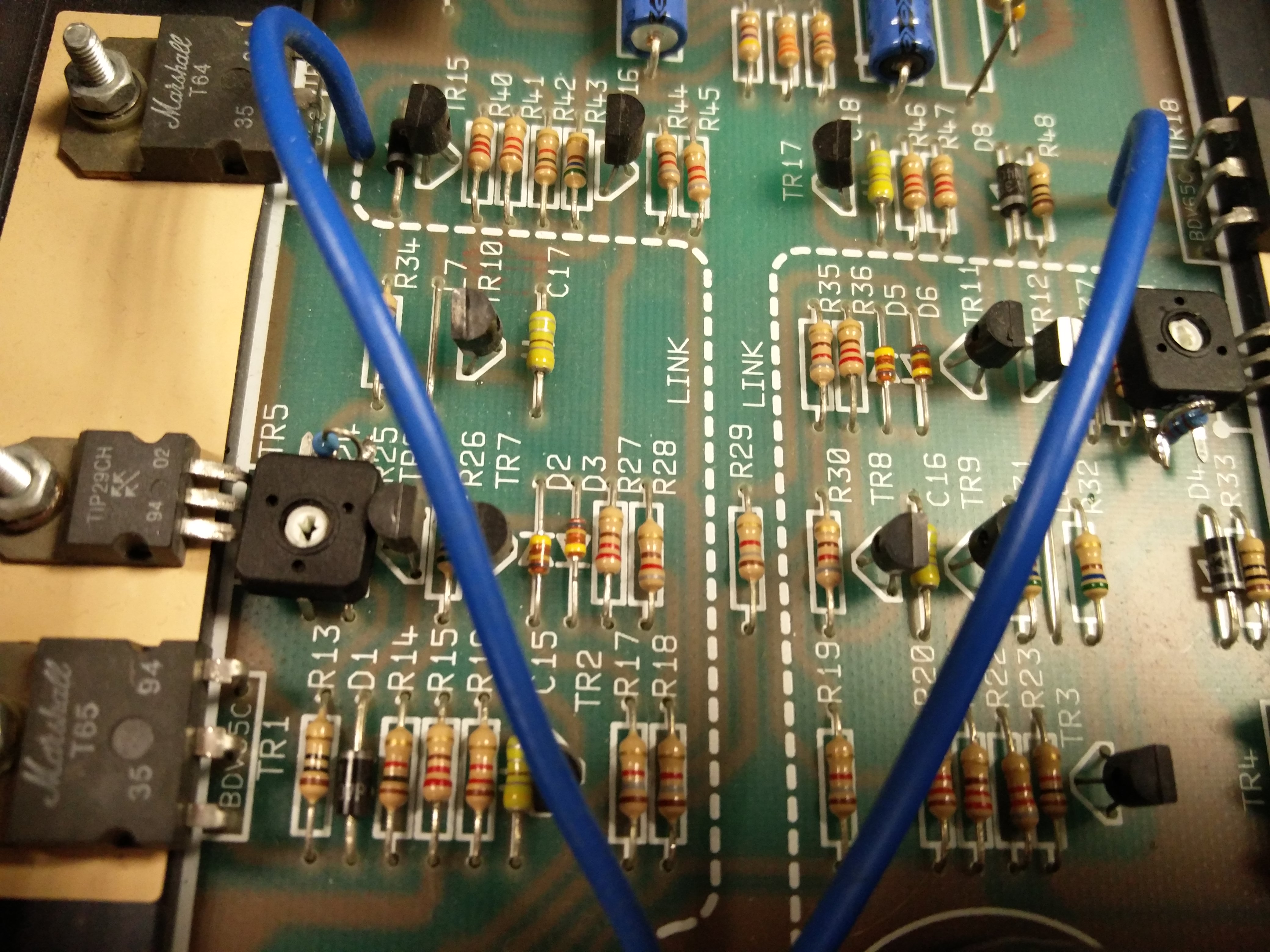
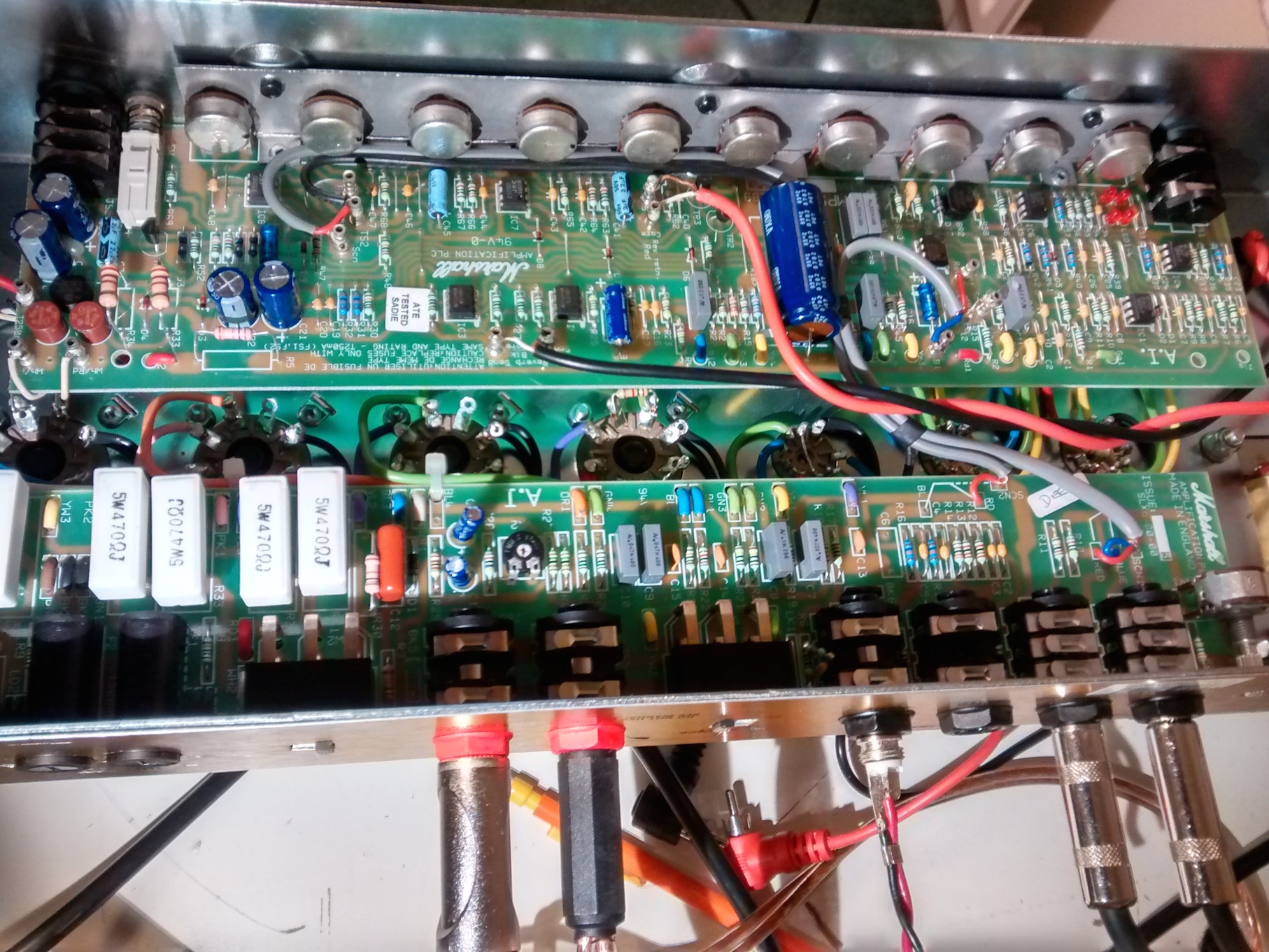
The amp is a Marshall Valvestate 8008 power amp. Despite the name it’s a solid state amp, intended for pairing with Marshall‘s hybrid and valve preamps. In this case it was being used as a keyboard power amp but was exhibiting an unpleasant distortion on notes. The distortion appeared regardless of input level and could be heard on pure sine wave or on clean keyboard sounds. However, when looking at the output waveform on his scope, it wasn’t visible, the waveform looked clean.Marshall Valvestate repair scope pic

First off, when looking at a the board out of the case we noticed that the reservoir caps were bulging, so I suggested some appropriate replacements. Leaking caps can lead to poor supply regulation, resulting in distortion. We also cleaned the crackly input sockets. However, none of this made a difference to the problem.

Whilst my friend’s scope hadn’t shown a problem, I looked at the problem on a different (better!) scope, the cause of the problem became more obvious. The distortion was a type known as ‘crossover distortion’ caused by a poorly biased amplifier. The first scope (shown in the pic) hadn’t had the vertical resolution to reveal the problem (although you can just about see it when you’re looking for it).

I do a lot of valve amp bias jobs, but don’t often end up having to rebias many solid state amps. This is because solid state output devices don’t often need replacing, and don’t degrade in the way that valve power amps do. Solid state amp manufacturers bias their amps at manufacture, and it normally doesn’t need to ever be adjusted. In this case, however Marshall hadn’t even biased the amp at manufacture, there was no bias pot, just a generic bias network, common to all devices. We checked another Marshall valvestate 8008 power amp, and the other amp exhibited no distortion, so this scheme obviously works for Marshall in some cases.Solid STate amp bias

I suggested adding a variable resistor to the bias network to fine tune the amp. The variable values have to be selected carefully in order to reduce the risk of amplifier damage if the bias pot fails. Once the pot was fitted, we dialed in the amp for optimum bias and completely removed the audible distortion.

If you have a Marshall valvestate repair, get in touch!


Marshall JCM900 repair – Ampworks Newark

Marshall-JCM900-repair-2 copy

This JCM900 repair arrived after the owner found that it was lacking in volume.

It’s a 2009 unit, two channel, with a 2203 type circuit on channel A and a higher gain circuit on channel B.

The problem appears to have been with the amplifier bias. Although the valves were matched, the bias on this JCM900 repair was set very high. The bias set the dissipation at about 95% – Marshall suggest about 70%. This causes the output to compress much earlier than would otherwise occur. Fortunately this is easy to fix.

I then offered to soak test the amp which is a means of testing the amp in the conditions it would be in rehearsal or gig. This is great for revealing those hard to find problems that would otherwise missed. It revealed a minor fault with the preamp – a crackle appeared behind the note transients. Since this was a relatively minor problem, the owner chose not to have it looked into.

I sometimes have been known to complain that some amp manufacturers give little thought to ease of repair – mesa boogie have had some stick from me in other reports. Some marshall repairs – thinking the DSL range in particular – are a bit difficult because of their complexity but this JCM900 repair is a delight to work on. They’ve really thought things through both in terms of reliability and ease of repair. It’s probably the easiest channel switching amp to repair that I’ve seen.

Although the channel A had a great plexi type tone, the owner isn’t a big fan of the Drive sound in ChannelB – he’s thinking of modding the amp to acheive the fabled Silver Jubilee tone so stay tuned – this one might turn up again.

If you have a JCM900 repair, please do get in touch.

Marshall – 2205 Repair

Marshall-Repair-JCM800-Repair

This 2205 repair came to me following an unsuccessful operation by another tech.

The 2205 were a new step for Marshall – and were one of a group of amplifiers that formed the ancestors of many channel switching amps we now take for granted – including amps by Mesa Boogie, Cornford, Hughes & Kettner, Marshall’s own JCM 2000 (DSL and TSL) and too many more to mention.

Modern Marshalls use relays for switching, but the 2205 uses a transistor array. Unfortunately it was that chip in this 2205 repair that turned out to be faulty. My customer tells me that there were 3 2205 versions, of which this is the second (1987 I think).

The original switching circuit has problems with popping that the original repairer had worked on. Unfortunately in doing so they had damaged the transistor in the switching chip that shorts out the distortion channel during clean mode. This meant that both channels passed the distorted signal. Oops!

I replaced the damaged chip and added a little extra anti-pop protection.

The amplifier also had hum problems, which were fixed by a partial implementation of the 3rd 2205 version. Swapping the triodes that were used for different functions (spring reverb and gain stage) reduced the hum to a very low level.

Disclaimer/Myth avoidance: Transistors and CMOS switches are good for switching some things, relays are good for others. Transistor switches don’t affect tone any more than relays if they’re correctly implemented.

If you have a Marshall 2205 repair job for me, please get in touch.

Marshall MG Repair – MG15DFX, Ampworks, Newark

Marshall Repair

No job too small! This Marshall MG Repair was a simple job – I wouldn’t normally take a lower cost amp in to repair – with the cost of a 2nd hand replacement being around the £50 mark, more than an hours labour and the repair becomes uneconomical for the customer. But this little Marshall MG had only a minor ailment – the emulated out was not working. It was a simple job to check the resistive network that links the preamp to the socket – no fault there. Cleaning the socket improved the situation, but didn’t fix it entirely so the socket had to be replaced.

Note to customers – always keep sockets that you don’t used lubricated with some cheap electrical contact cleaner – only a couple of quid spent, the pot last for ages and you can clean guitar pots and switches as well as input sockets. Never use on a live amp.

Marshall MG repair MG15DFX

If you have a Marshall MG Repair job, get in touch.

Marshall Repair – JCM2000 DSL100

Marshall Repair

This Marshall Repair was brought to me with one of those sneaky ‘hard to find’ problems. The amp was blowing fuses when the customer was playing it. He’d taken the amp to another repairer who hadn’t found any problems. Unfortunately the amp continued to blow fuses.

Guitar amplifier repairs of this kind often have to be treated in a different way. After an initial examination, opening up the amp and checking for any burnt components or loose joints I placed the amplifier on soak test. This involves playing a representative signal through the amp into a dummy load in the conditions that the amp was in when it was blowing fuses. During this soak test I observed that under certain conditions one of the power valves was sparking internally. I swapped the set of valves, re-biased and then placed the amp back on soak test. Since the amp wasn’t blowing fuses or sparking any longer, I decided that it was ready to go.

If you have a Marshall repair job that needs doing, please get in touch via the contact page.