
I’m just quickly leaving some infromation about a Philips MyLiving Fremont LED light repair in the hope that it will help someone else!
Ah, the joy of being a repairer. No sooner have I finished a hard week of repairing guitar amps than I must power up my soldering iron again to fix the broken kitchen light in our family home.
LED lights are indeed more reliable than their counterparts, but only if they’re made properly! I’m rather disappointed in Philips. We had one of the single spots replaced under warranty after a few months. Then two spots out of a four spot bar then died within warranty. This second time the unit was obsolete so Philips offered a completely different unit (different mounting and non matching appearance) as a replacement, which we declined, so we were stuck with them and I decided to repair them myself.
The first one was a nightmare to fix as I tried to reuse the original LEDs and then it took ages to find a suitable part. But the second one was relatively easy after I’d learned the lessons of the first. So here’s the right way for any other poor sucker who has bought one!
The LEDs that I used for the repair were the Lumileds L130-27800CHV00001. Specs below:
- Colour Temp (CCT) 2700K
- Colour index CRI: 80
- Luminous flux: 107lm
- Efficiency 136lm/W
- Current 17mA
- Voltage 48V
- Size 3x3mm (1210)
- Package 1210
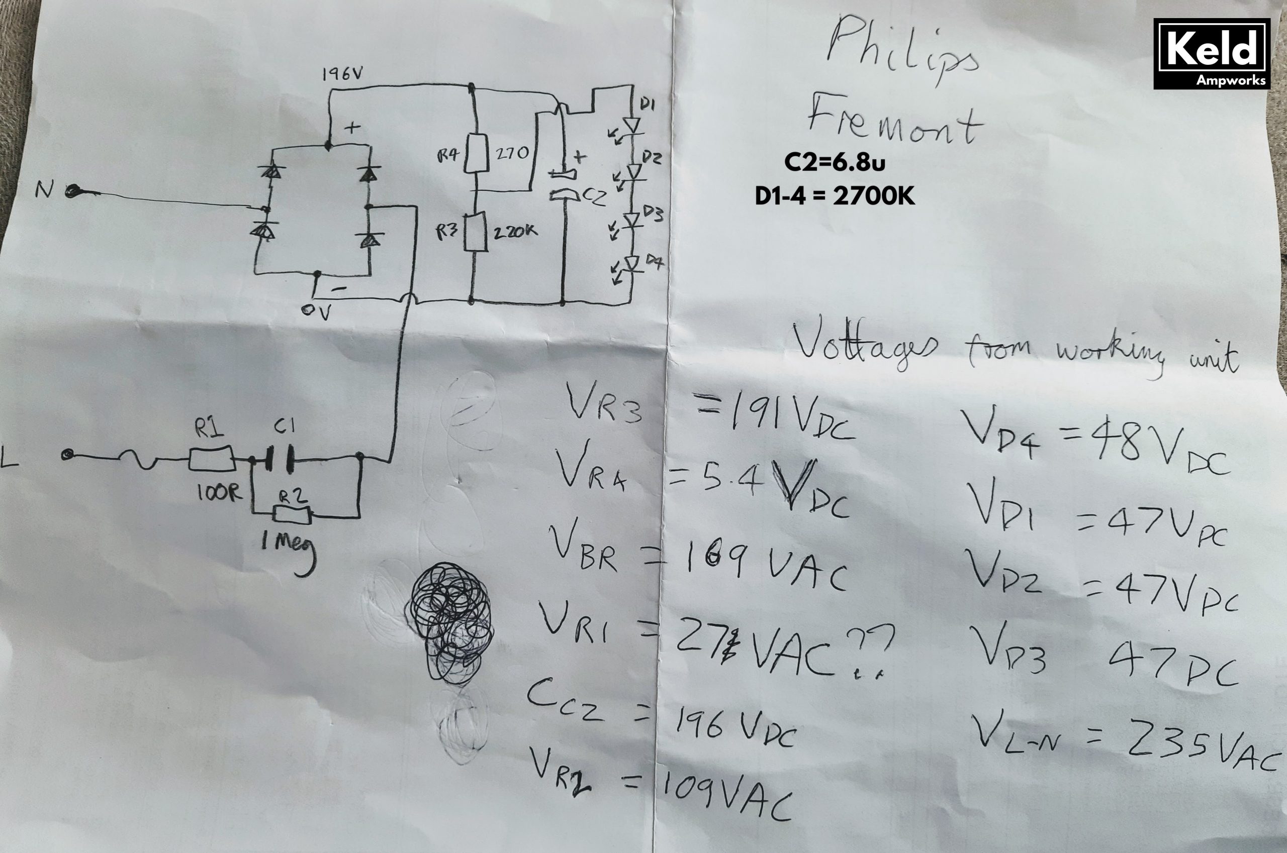
Having lived my whole career in the audio sector I didn’t even know Vf=48V LEDs were a thing, I’m used to them being Vf=2-5V parts! I determined that the drop through each was 48V by testing a working unit, results below.
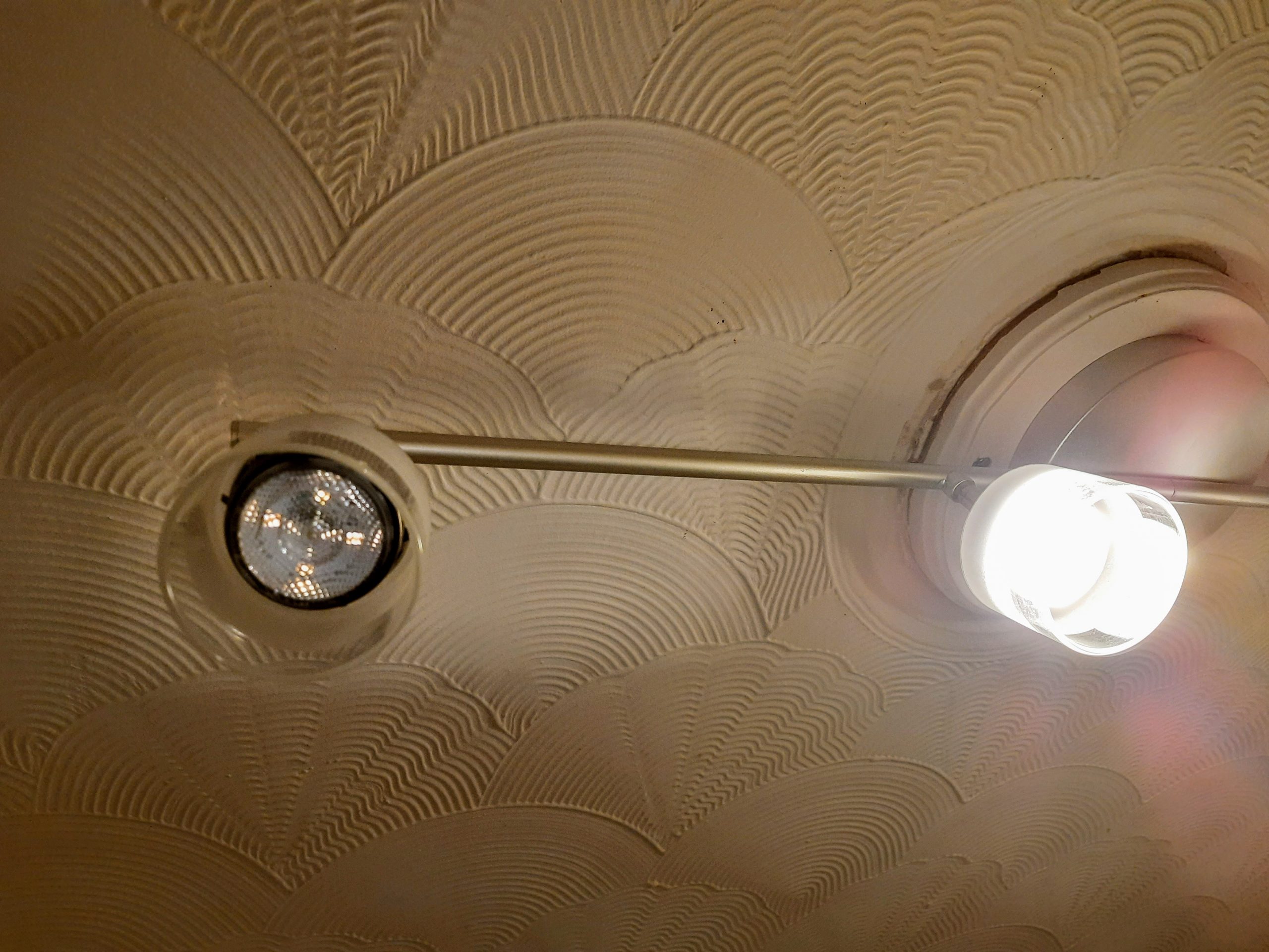
The LEDs don’t seem to fail, the failure is in the solder connection connecting the LEDs. Because the LEDs are in series, one solder joint failure causes the whole light to go very dim (or off).
This is a potentially dangerous process, so only attempt if you know what you’re doing. The lights are VERY bright and can affect your vision. I wore sunglasses for testing. Really, I did!
To disassemble:
- Turn off mains and
- Remove from ceiling
- Check safety with multimeter
- Disconnect L and N wires
- Use a 2mm hex allen key to loosen the head of the light and thread the wires out, being very very careful not to snag the wires
- Use a flat blade screw driver to gentle push back the metal springs holding the glass cover on and remove the cover
- Use a flat blade to push the metal spring ring over the tabs and remove it completely
- Unscrew the lens and remove the lens, and metal insert from the plastic case and thread the wires out. You may have to cut off the crimps if it’s a 4 bar.
Here’s how I diagnose which LED connection is at fault:
- Use a 48 or 50VDC supply with some sharp multimeter probes. Set the current limit to 50mA. Make sure the probes don’t touch and short your supply!!
- The PCB is well labelled. Prod the sharp positive probe into the Anode (A) pad on the PCB and the sharp negative probe into the cathode (K) pad. If the LED illuminates then it’s OK.
- Test each LED in turn until you find the faulty LED connection.
The LED pads don’t touch the edge of the part so replacing them is tricky and not for the inexperienced. Here’s how:
- Remove the LED using a hot air blower / chipquik or your method of choice. The LED pads don’t touch the edge of the part so this is tricky to do without damaging or discolouring the LED. Heated SMT tweezers might work if you use them to heat the pads rather than the component but they’re not ideal.
- You could test the LED by laying it face down it on a small piece of clear plastic and using your 48V probes to illuminate it. It’s probably still working – all of mine were. If the LED is discoloured upon removal then bin it anyway – you’ll be able to see the discolouration through the lens and it might affect the colour – I’m not sure!
- Clean the flux from the PCB (again, the discolouration is visible if you don’t).
- Tin the PCB pads and tin the component pads, using only a VERY SMALL dab of solder.
- Put a small dab of flux on the PCB pads
- Heat up the larger cathode (K) pad on the PCB and very quickly place the component, observing orientation. Hold the part in place pressing lightly with tweezers until you can feel the solder melt and the part flow into place. It should be almost flush on the cathode side but there will be a small incline towards the anode because you tinned it.
- Heat up the anode pad and add a small amount of extra solder. Due to its smaller size this pad should make the joint easily.
- Test with your 48V probes.
- If you’ve got a mains safety claw you could test the whole light on mains AC. Don’t do this if you’re not comfortable working with un-isolated mains.
- Clean flux off the PCB again if necessary.
Hope that helps someone who needs help with a Philips MyLiving Fremont LED light repair. I’m not interested in repairing these for money, I’m an amp guy only. But I’ve got a few of the LEDs spare so if anyone needs them pop me a message and I can list them them for sale on www.rsdsound.co.uk .