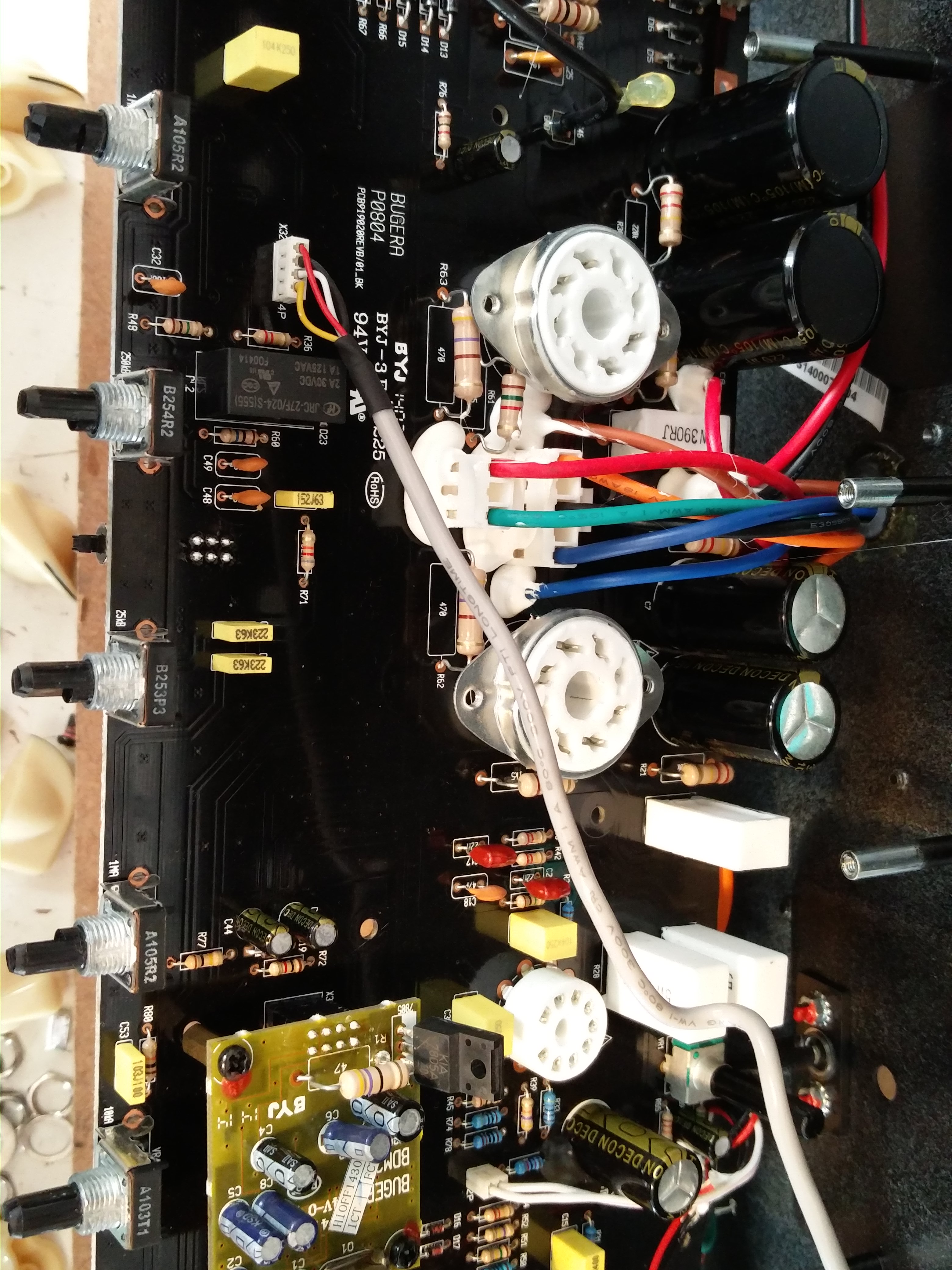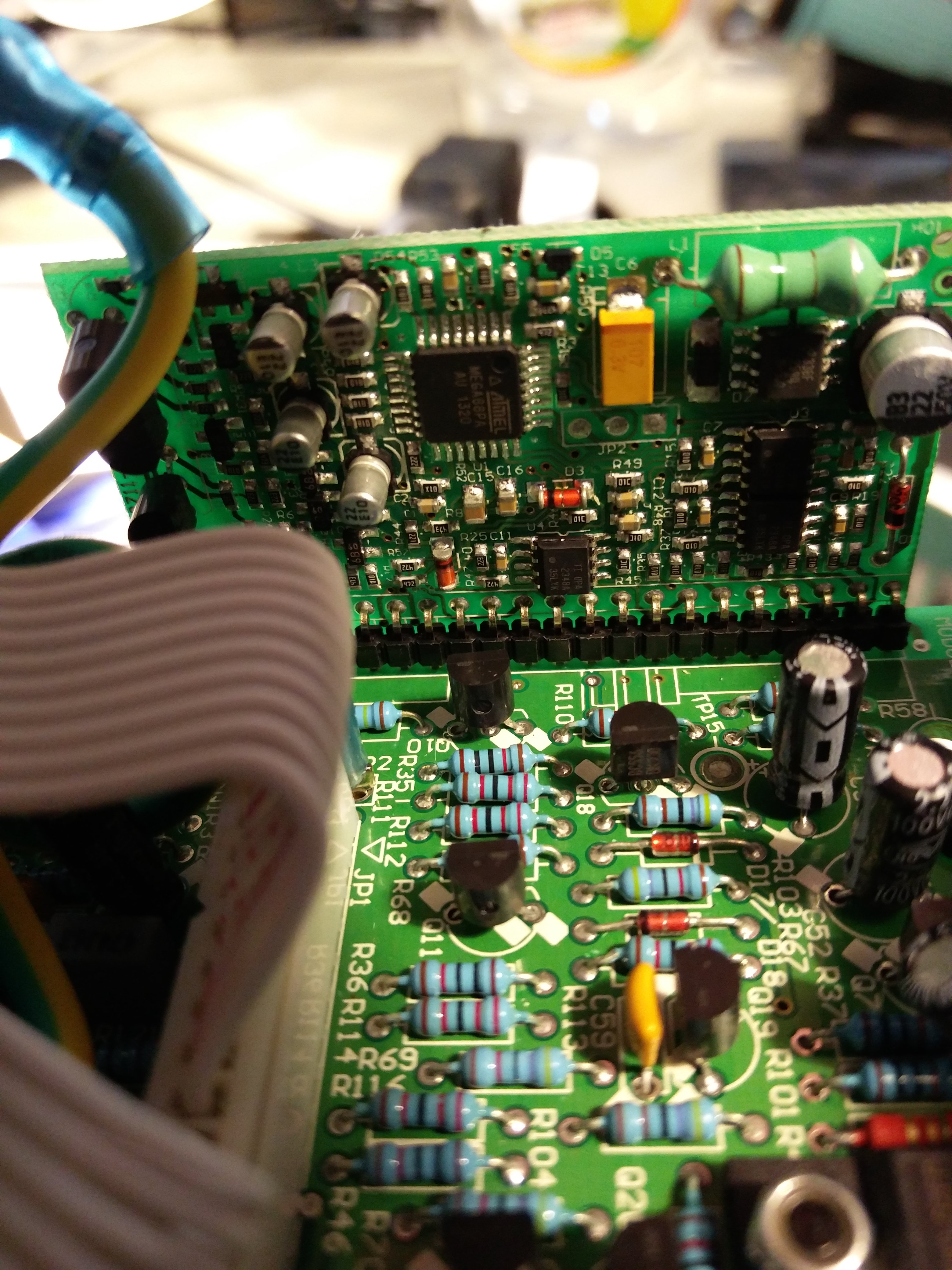
Marshall JCM 2000 Replacement PCB – TSL100 and DSL100 bias drift repair using the ROS-2000 board

Marshall JCM 2000 Replacement PCB

Marshall JCM 2000 – ROS-2000 board design overview

We’ve had a few questions about the ROS-2000 replacement board that I designed for the Marshall JCM 2000, so I thought it was worth putting a proper nerd level explanation together. Buckle up!

The project was a collaboration with Stewart at www.valvetubeguitaramps.com and it’s available exclusively from his website at the following link ROS-2000 PCB for JCM2000 Amplifiers – Valve Tube Guitar Amps

This isn’t a quick overview – it’s very much a “what we did and why” from a repair and design point of view. Buckle Up!

What the board is (and why it exists)

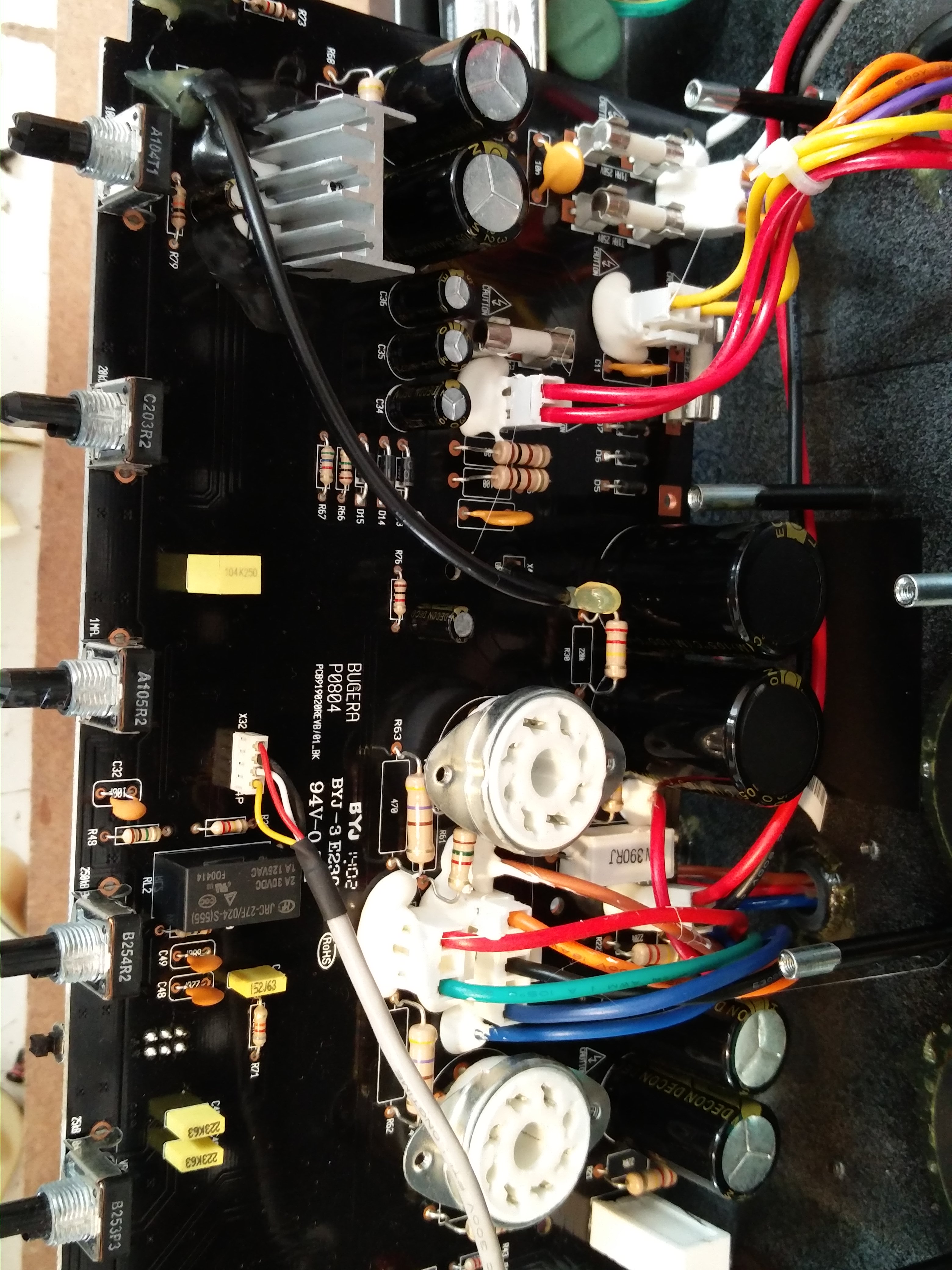
The ROS-2000 is a replacement for the original Marshall valve PCB, which is well known for a few issues – we mostly see them with the bias drift issue, in which a conductive board causes a thermal runaway, killing the EL34 valves.

The aim here wasn’t to reinvent the amp, just to fix the weaknesses properly and make something that’s reliable long-term.

Everything was designed here at Keld Ampworks in Nottinghamshire and manufactured in the UK, rather than partially outsourced and “finished” locally. Stewart at vtga spoke to a load of UK manufacturers to select the best for the job. In the end we settled on a manufacturer in Hastings, UK (1066!) to build the main part of the board and completed the configuration here in Keld Ampworks or at Stewart’s site on the beautiful North Yorkshire coast.

Component choices

Across the board, we’ve uprated pretty much everything:

  • Signal resistors are metal film (lower noise than carbon types)
  • High-voltage resistors are 2W rated for extra headroom
  • Film capacitors are Wima
  • Ceramics are Vishay / Murata
  • Electrolytics are Rubycon / Nichicon / Nippon Chemicon

Nothing exotic, just good-quality, proven parts with sensible ratings.

Whilst designing this board I noticed that there’s a capacitor in the original design that ends up reverse-biased in certain switching modes. That’s been corrected here, as it’s not something you want for long-term reliability, although I haven’t seen it cause failures!

Fixing the original fault (bias drift)

The big issue on these amps is leakage between high voltage (HT) and the bias supply.
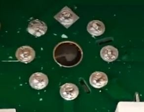
PCB slots to fix the bias drift issue on the Marshall JCM2000

That’s addressed in a few ways:

  • Physical slots cut into the PCB to increase isolation
  • Much greater spacing between HT and bias traces
  • Careful routing so the two don’t run even slightly close together

There’s also an external link used to route HT rather than crossing sensitive areas of the board.

Despite extensive design reviews we still had a nervous moment when we ran the board up for the first time, but the result was no measurable bias drift, even under quite severe heat stress testing.

Heat management

The original board uses a bridge rectifier for the heater supply, which runs hot.

That’s been replaced with four discrete diodes, spaced for airflow.
They run cooler and don’t dump heat into the PCB. This issue originally caused hum noises in the clean channel on the JCM 2000 boards.

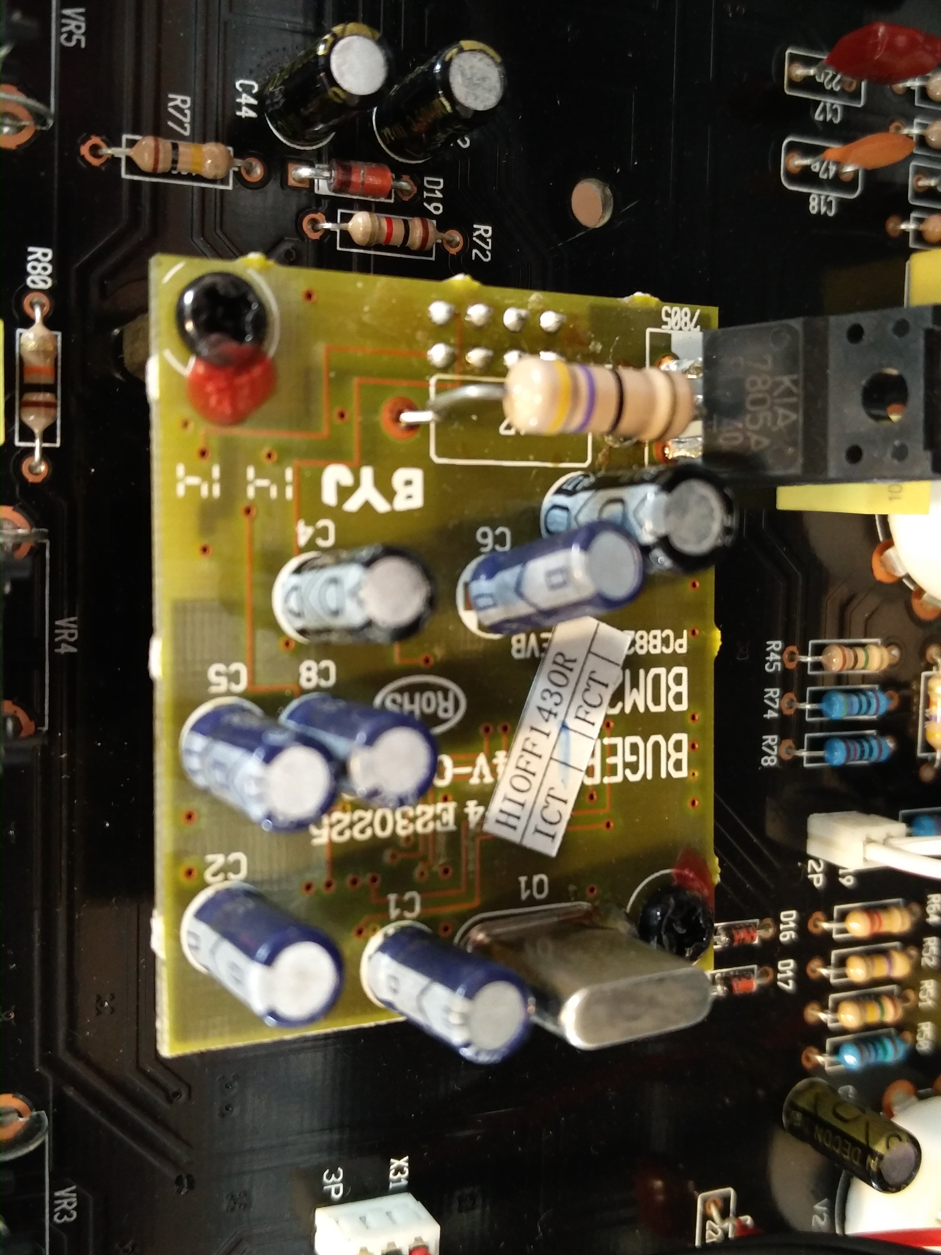
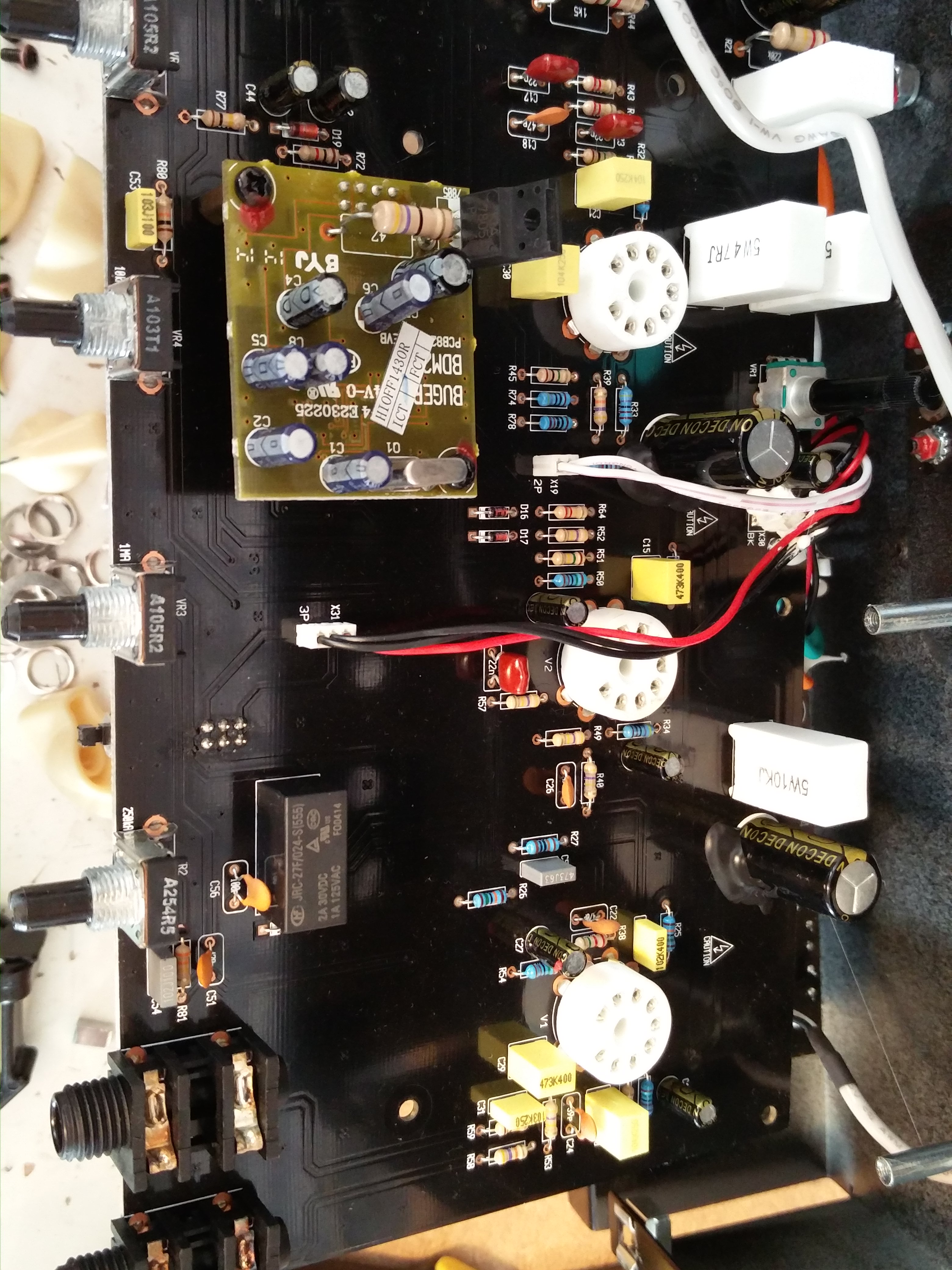
Surface Mount Components

Surface-mount tends to get a bit of a bad reputation in valve amps, so it’s probably worth addressing that directly.

They’re not used here as a cost-saving exercise – in fact our choice to use surface mount actually added cost, as we had run 2 manufacturing passes rather than a single through-hole build.

The only reason they’re used is because, in those specific parts of the circuit, they’re simply the right choice and reducing the component footprint on the switching circuit allowed us more space elsewhere to eliminate cross talk and heat disipation issues.

All of the surface-mount components are in low-voltage areas, with nothing seeing more than around 10–12V and no meaningful heat being generated. In that context, they’re perfectly reliable and allow for a cleaner layout, particularly in keeping the ground plane intact, which helps keep noise down.

Where there’s high voltage or any real power dissipation, it’s all traditional through-hole parts as you’d expect.

So it’s not a blanket approach – just using each type of component where it actually makes sense. Engineering is about using the right part for the job, not dogmatically rejecting technology based on internet nonsense! Sorry guys!
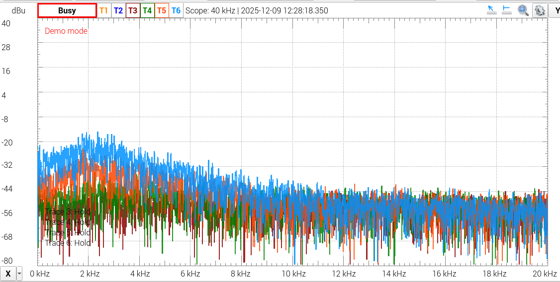
Reducing noise on a JCM2000 with the ROS-2000 PCB

Layout and grounding

Connector positions are kept similar to the original, so installation is straightforward and doesn’t require reworking wiring looms.

On the PCB itself:

  • Surface-mount parts are used only where appropriate (low voltage, no heat). We
  • Through-hole parts are used where needed for robustness
  • A full ground plane is used on the underside

There’s a lot of debate about ground planes in valve amps, but in practice, done properly, they reduce noise and interference – and that’s been borne out in testing. In my previous engineering career before Keld Ampworks I spent a substantial amount of time testing audio euqipment for harsh EMC environments. Ground planes reduced interference IN EVERY SINGLE CASE. That said, inexperienced PCB designers might make mistakes with running low impedance ground panes near radiated sources to cause problems. Fortunately, we avoided that and this unit is measurably quieter than other options as a result of sensible tracking and the ground plane.

The other common complaint about valve amps is that “LEO FENDER DIDN’T USE A GROUND PLANE”. Well Leo didn’t use his amps near wifi, or wireless rigs, or lighting rigs with SMPS sources. I’ve played on stages where ’boutique’ amps have been plagued with RF interference noise whilst my own ground plane amps have stayed beautifully quiet. It’s just good engineering, folks.

Mechanical reliability

A couple of small but important details:

  • Raised components use ceramic spacers, so they can’t bend and short during shipping
  • Components are secured with non-acetone silicone, not hot glue (which goes brittle with heat)

These are the kinds of things that don’t show up immediately, but matter over time.
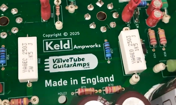
Uprated screen grids in the JCM2000 upgrade PCB

Other improvements

A few additional tweaks:

  • Screen grid resistors uprated to 1k5 to extend valve life
  • Flyback diodes added to protect the output transformer
  • Improved heater trace layout and balancing – see previous comments about understanding how to design PCBs with ground planes!

None of these change the sound in any way, but they do make the amp more robust and lower noise.

Testing

We tested the prototypes extensively to make sure that they matched up to the most recent (best) Issue 20 Marshall PCBs. The frequency responses matched up perfectly in all channels on our test TSL100 and our test DSL100. We tested it at every knob extreme and also tested the Tone shift, boost/mid boost deep and presece performance. The waveforms also matched up in clean and clipping performance. We then tested the noise and found that we had indeed managed to make the unit slightly quieter. Ground plane, folks.

Have you waded through all that? I’m impressed.

This isn’t about changing the character of the amp, it’s about making it behave properly.

The original design works, but it has some weak points. The ROS-2000 board addresses those with better layout, better parts, and a bit more attention to how things behave under real-world conditions (heat, vibration, long-term use).

Hope that was useful, if you like what you see, please do head on over to Stewart’s website here: ROS-2000 PCB for JCM2000 Amplifiers – Valve Tube Guitar Amps

If anything’s unclear or you’ve got specific questions about the design, feel free to ask.
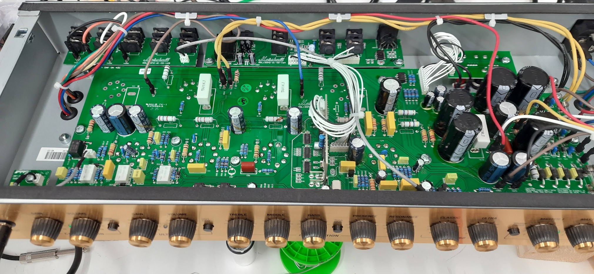
Marshall DSL40CR

DSL40CR repair

I don’t often see a DSL40CR come through with this kind of erratic behaviour – it was one of those jobs that kept me scratching my head until the real root cause showed itself.

The Symptoms (as described by the customer)

  • The amp would unpredictably switch from the Clean channel into Overdrive (OD) without touching the footswitch or front panel. I noticed that putting the amp in standby would instanly trigger the fault
  • Otherwise, it sounded fine: the valves were healthy, the output stage appeared to behave, and no obvious catastrophic faults were present.

Removing a valve changes the power supply behaviour, so that’s where I started.

What I found was subtle: the control supply (low voltage rail) was not rock solid. The rail that feeds the preamp switching logic and control electronics was sagging or shifting, just enough so that under certain conditions the amp would interpret it as a switch command.

Once the control rail wobbled or dipped, the channel logic would misbehave and flip the amp into OD mode. A surprising symptom, but less surprising once you realize how sensitive those digital / switching circuits can be when their supply is out of spec.

I’m lucky enough to have a friend who knows the technical issues with this range of amps better than literally everyone else in the world. He suggested I look at the power supply section on the rear board as this is the most prone to sagging.

In addition, during the inspection I noted a few design / build quirks that I’ve occasionally encountered in the DSL40CR family (and in other Marshall amps), which may be part of why these amps sometimes exhibit low output or noise issues:

  • Low power / reduced volume: I’ve seen DSL40CRs (and sibling models) drift into low power mode, often caused by conductive glue traces (flux residue or glue meant for mechanical stability) creeping between printed traces, forming parasitic leakage paths. These “hidden conductive paths” can robs bias or collapse gain subtly, especially under heat.
  • Noise issues from 1 M grid resistors: Some of those 1 M grid or grid‑stop resistors in the preamp are notorious for turning noisy over time, especially when they drift in value or have internal contamination. That adds hiss or crackle, especially on the quieter parts of the circuit.
  • Shorting via ceramic resistor bodies: I’ve even found situations where the body of a ceramic resistor is so close to a high voltage (HV) board trace that it arcs or shorts under certain conditions – e.g. if the resistor’s coating is cracked, or there’s flux residue, or simply vibration has shifted things. That can cause weird intermittent behaviour, grounding, or leakage between circuits.

So, while the main symptom in this unit was the channel‑switching, it was wise (and necessary) to check for all these known weak spots in the DSL40CR line.

After these repairs, the DSM40CR stayed rock solid in each channel: no more phantom switching. I ran the amp through its full range of channels, settings, footswitch tests, power cycling, and warm-up cycles. Then I subjected it to a soak test at gigging levels for a good hour or two – it remained stable, no drift, no switching anomalies.

I also measured output power and bias and compared it to spec – it was right in the expected ballpark (i.e. no low‑power symptoms). That confirmed that the power stages and bias were healthy.

If you have a DSL40CR (or any Marshall) behaving oddly – randomly jumping channels, volume sagging, noise creeping in – don’t assume the worst (i.e. bad valves). A disciplined service + power‑supply / control circuit check is often all that’s needed to bring it back to life. Please do get in touch

Hughes & Kettner Switchblade Amp Repair

I recently repaired a Hughes & Kettner Switchblade amp that had a shorted mains transformer, causing power failure. Thankfully, I sourced a replacement transformer from a genuine parts supplier, ensuring top quality for the repair.

After installing the new transformer, I performed a full service, which included cleaning key components and checking all connections. I also replaced the old output valves with a new pair of EL34s to restore the amp operation.

Following the Hughes & Kettner Switchblade amp repair, I tested the amp at various volumes, and it delivered as expected. The owner was thrilled to have their amp back, ready for upcoming gigs.

If your amp needs attention, don’t hesitate to get in touch—your gear deserves the best!

AER Compact repair

AER Compact repair

Recently, I had the pleasure of repairing an AER Compact 60 amp that was experiencing frustrating audio dropouts. The owner had noticed that sound inconsistently faded in and out during performances, which can be a nightmare for any musician.

To diagnose the issue, I conducted a soak test—a method that involves running the amp at gigging volumes for an extended period. This technique helps reveal intermittent faults in the AER Compact that might not be evident during a brief test. During the AER Compact repair I monitored the amp, it became clear that the dropouts were linked to oxidized switches. These switches, often overlooked, can degrade over time, leading to poor connections and sound cut-offs.

After cleaning the affected switches and ensuring all connections were secure, I re-tested the amp. The result of the AER Compact Repair? A solid, consistent output with no further dropouts. The owner was thrilled to have their AER Compact 60 back in perfect working order, ready for the next gig.

If you’re facing similar issues with your gear, don’t hesitate to reach out for a repair!

Blackstar HT100 repair

Blackstar HT100 repair

This Blackstar HT100 repair was completed for the co owner of an exciting new Grantham based venture ‘Melody Music Rooms’ in Grantham.

Melody music rooms are a rehearsal space, recording facility and teaching space located on Westgate in Grantham . It’s the brainchild of a group of Lincolnshire and Nottinghamshire music teachers who wanted to provide better music services in the area. Not just a building, they run jam nights and busking sessions featuring local young (and old!) musicians. It’s great to have these guys raising the profile of live music in the area, so do check them out on https://www.facebook.com/melodymusicrooms/.

I’m told that this amp has played Wembley(!) as the owners of Melody Music played some high profile support gigs with their old band. It had been retired when it started blowing fuses, but the owner wanted it brought back to life for the new Melody venture.

There were a couple of valves to replace and the amp had blown the bridge rectifer diodes. Unfortunately Blackstar don’t provide schematics for their amps so it’s always a bit of a tough job repairing Blackstar gear.

Normally at this point I’d put a clip of my repair video, but here’s the repaired amp being used in the studio at Melody Music Rooms.

If you need a Blackstar HT100 repair, please drop me a line.

Polytone Minibrute Repair (Minibrute III repair)

Polytone Minibrute repair

This Polytone Minibrute Repair came in from a Lincoln customer with an obnoxious hum problem. This unit is probably form the 1980s

The issue was solved by adjusting the output stage bias point and improving the connection between the screw mount power supply capacitors and the power amp stage.
polytone minibrute iii repair
The amp is a bit of an oddball in terms of construction, with the preamp contained in the top of the amp, and the power amp in the base of the unit. The power amp unit is held together by the capacitor screws and two large heatsinks.

If you need a polytone minibrute repair, please get in touch.

Bugera Repair – V55

Bugera repair V55

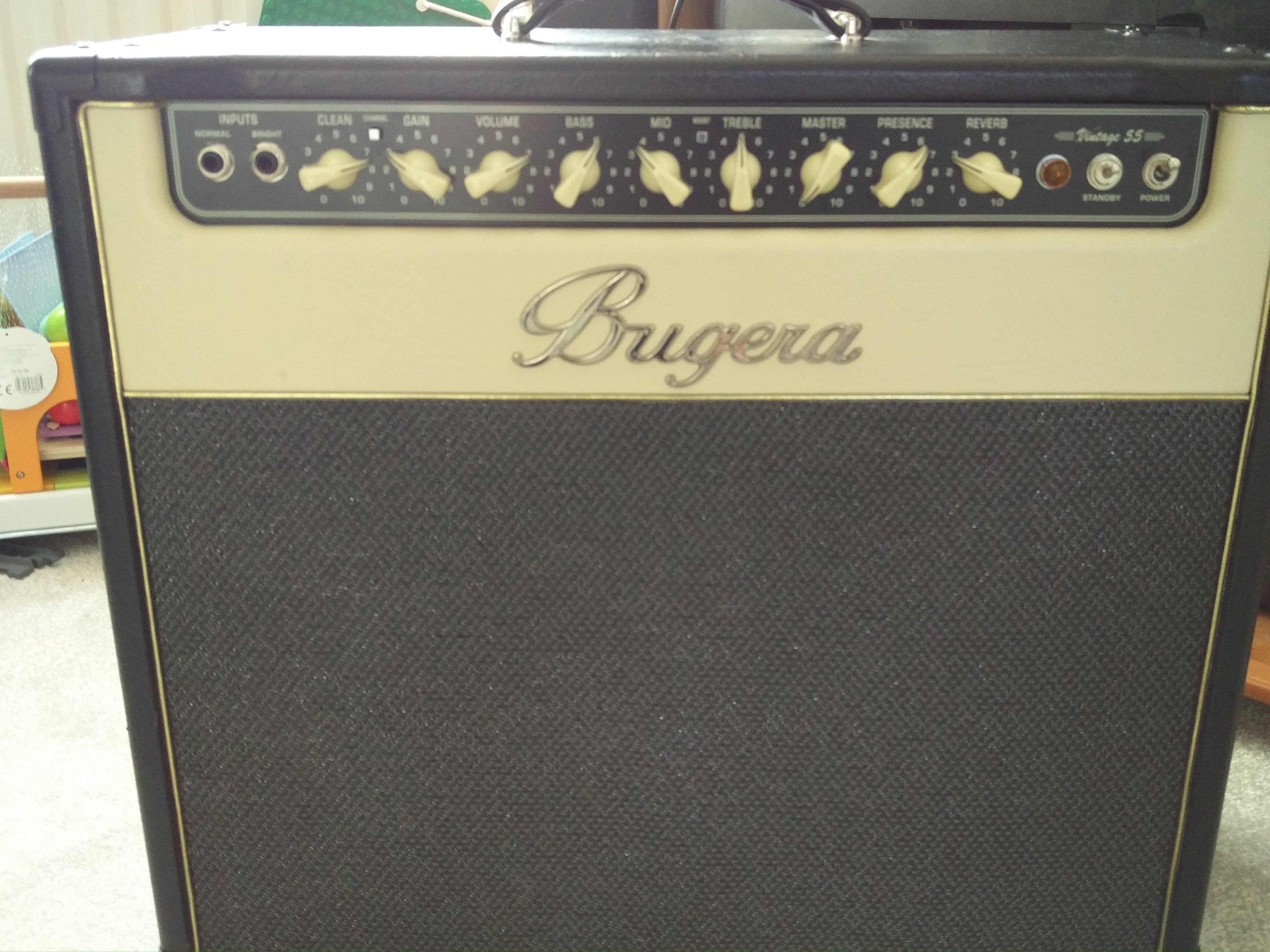
Turned this Bugera repair around quickly in time for it’s owner’s gig in Skegness. The amp is a vintage 55, or V55.

The amp was brought in for a standard 2 hour service, with a few particular points of attention. The owner had noticed that the clean channel was overdriving much sooner than previously. Also the standby switch was broken.

After testing the valves in my valve tester I discovered that the cause of the clean channel change was a very worn Shuguang preamp valve. I replaced it with a new Tung Sol 12AX7. I also discovered that one of the Bugera branded power valves was also faulty, requiring a change of both power valves to EHX 6L6s and a rebias.

Bugera repair V55Bugera repair V55 - replace standby switch

I’m not a big fan of Bugera’s bias control – a phono output that makes the bias voltage externally accessible and a little finger trim pot. The trim pot is a nightmare to adjust – screwdriver turned pots are much more accurate. And the phono socket exposes a relatively large voltage of between -40 and -80VDC. Also, the bias voltage isn’t a very good way of measuring bias (see this post by Aiken amps). Behringer use it as a way of encouraging you to buy their pre-graded valves. I use the most accurate cathode current method of biasing with a multimeter and a set of custom probes. I set the bias to 38mA, which is 70%.

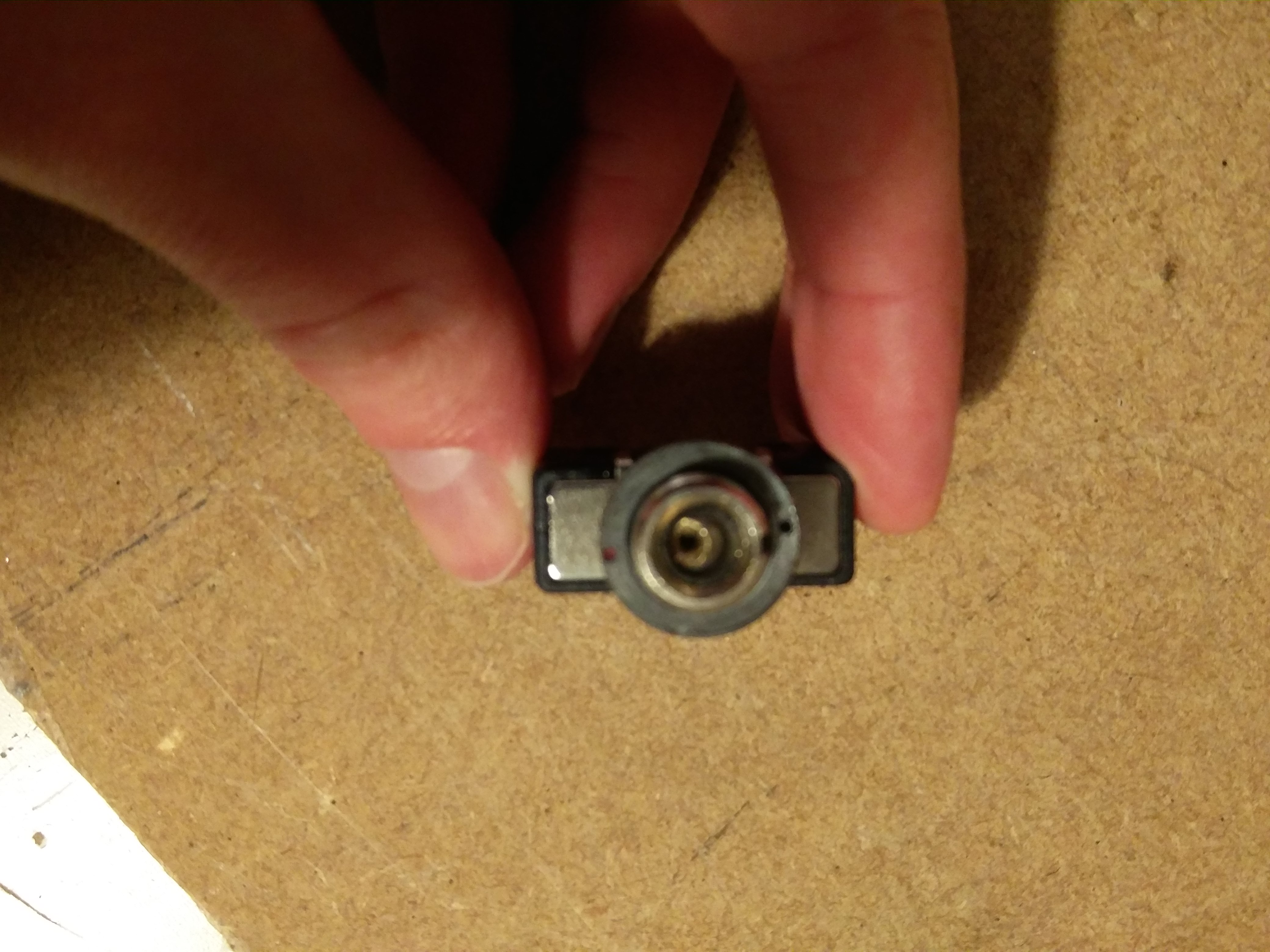
A specific request on this Bugera repair was to replace the damaged standby switch. It was a quick and easy job – as seen in the image. I often hold generic parts like this in stockin order to fit a variety of amps, or I can always order specific pieces in to suit an amp’s aesthetic.

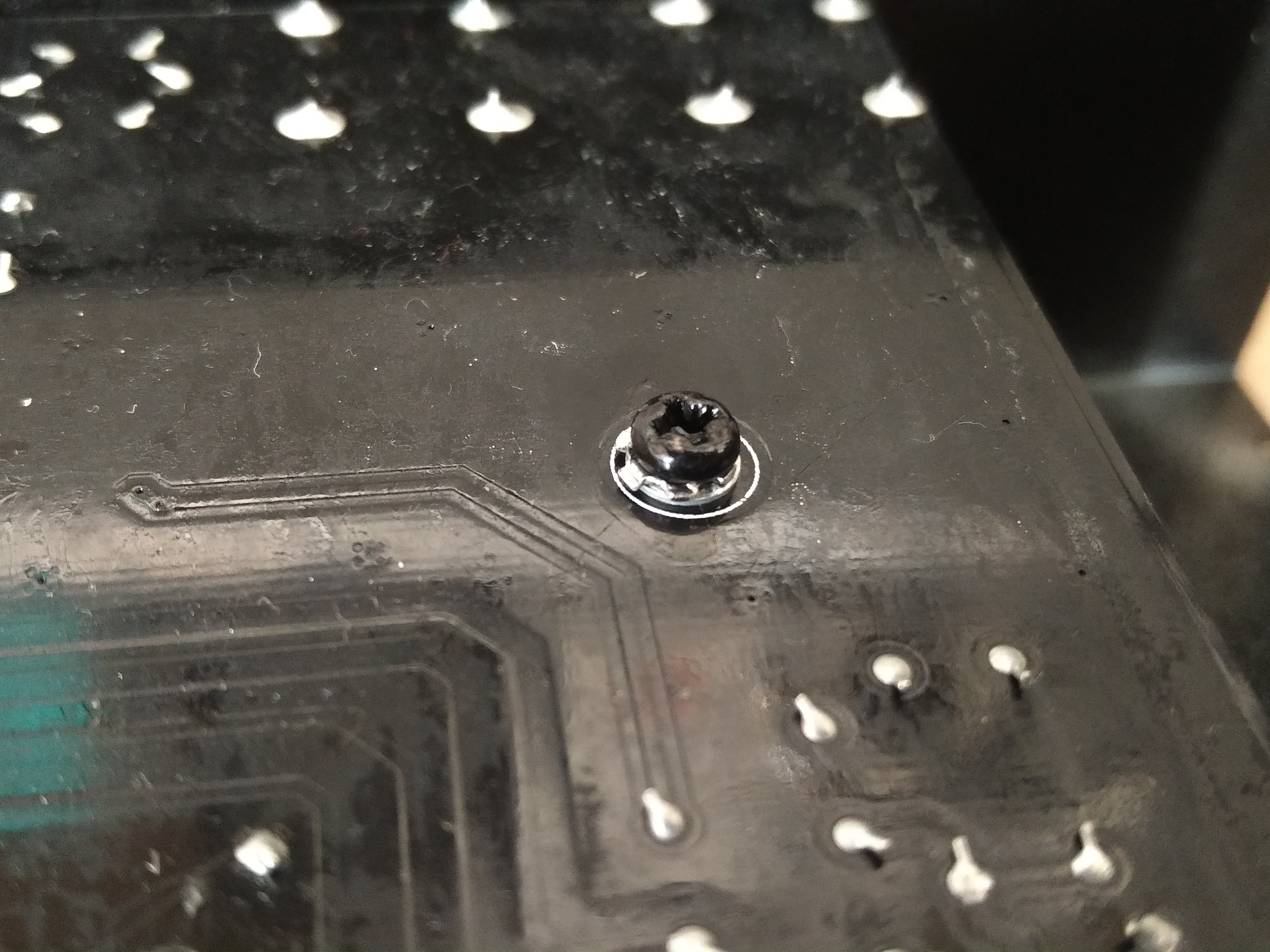
Bugera repair V55 verdigris on PCBBugera repair V55Upon inspecting the board I noticed a number of areas that were corroded – in the picture you can clearly see the Verdigris (copper carbonate) on component pins and PCB pads. I desoldered these pads and freshly resoldered them. I also spotted a couple of dry joints on valve bases and fixed these up. After this stage I refitted the PCB.The original screws were secured with thread lock, so instead I added a toothed washer and a plain washer – many manufacturers and repairers omit the plain washer, but this is very important in order to not damage the PCB surface and thus loosen the screw.


I was interested to note that the amp uses a ‘Turbosound designed’ speaker. This is because Bugera and Turbosound are both owned by Music Group (Behringer). The amp also uses a V1000 cool audio (I think this is anothewr behringer brand) multifx chip and a V4220M codec on a mezanine board to create the digital reverb.

If you have a bugera repair job for me, please get in touch.


Bugera repair V55

Bugera repair V55Bugera repair V55

Bugera repair V55

Fender Blues Junior Repair – Urgent Repair

Fender Blues Junior Repair

This Fender Blues Junior Repair was an urgent repair job for a London based guitarist. I got the amp at 23:30 on the Saturday after a gig in Southwell near Newark and had it diagnosed by 11:15 the next morning before he returned to the ‘big smoke’.

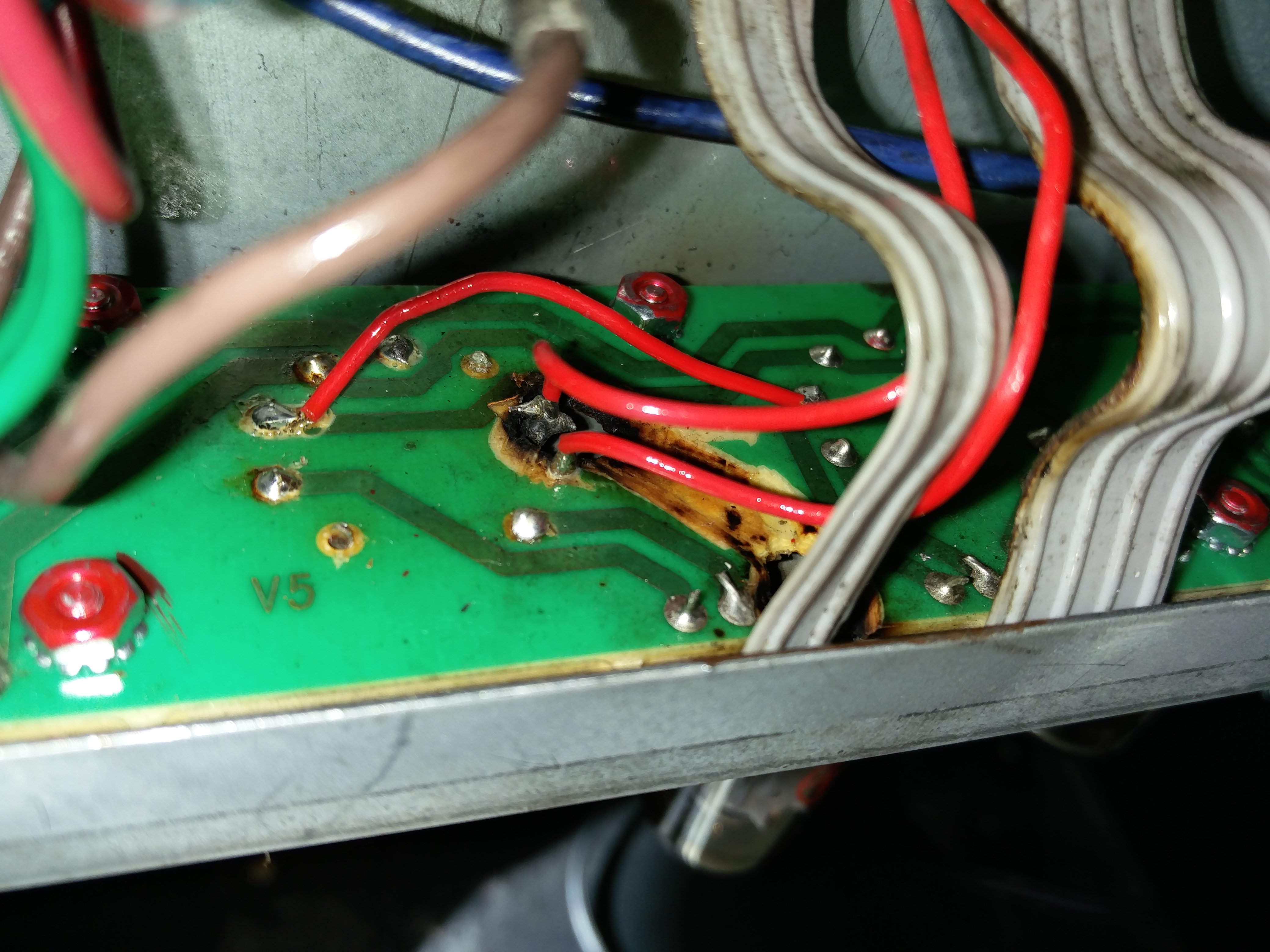
Actually, big smoke was obviously a problem that this amp had experienced in the past as can be seen in the image. A power valve had blown and seriously damaged the PCB. Unfortunately the amp had been taken to a Nottingham music shop for repair and I’m afraid they didn’t know what they were doing!

Whoever fixed it has did something weird and wired up a valve pin that doesn’t connect to anything – it should have been going to the cathode, although they have then wired up the cathode separately. There’s no actual harm with this, it just suggests they didn’t know what they were doing!
They also not secured the valve base very well, so it rocks and lifts the pins when you remove or move a valve. This has started to pull up a PCB track on one of the power valves. This will almost certainly cause problems in the future.

I’ve performed a temporary fix on the problem pin 7 by shaving the solder mask off the copper and adding more solder to give the pin an extra connection.

I recommended rewiring the whole power stage at some point in the not too distant future because the amp is a bit of an accident waiting to happen. Unfortunately there wasn’t time to perform the full repair before the customer left for London.

However all this was a chance discovery. I was actually asked to look at a faulty spring reverb on this blues Junior repair. The problem turned out to be with the tank itself. I checked continuity and ground on the cables and observed signal getting to the tank and nothing coming out.

I’ve got a short Accutronics reverb tank kicking around from an amp I gutted so I thought I’d try it, The impedances didn’t match and it sounded terrible with the Blues Junior! But it proved that this was the only problem with the reverb.

The good news is that the customer could buy a spring reverb unit and fit it himself – you only need a screwdriver.

The customer was kind enough to leave a review on my Facebook page.

If you have a Fender blues junior repair, please get in touch.

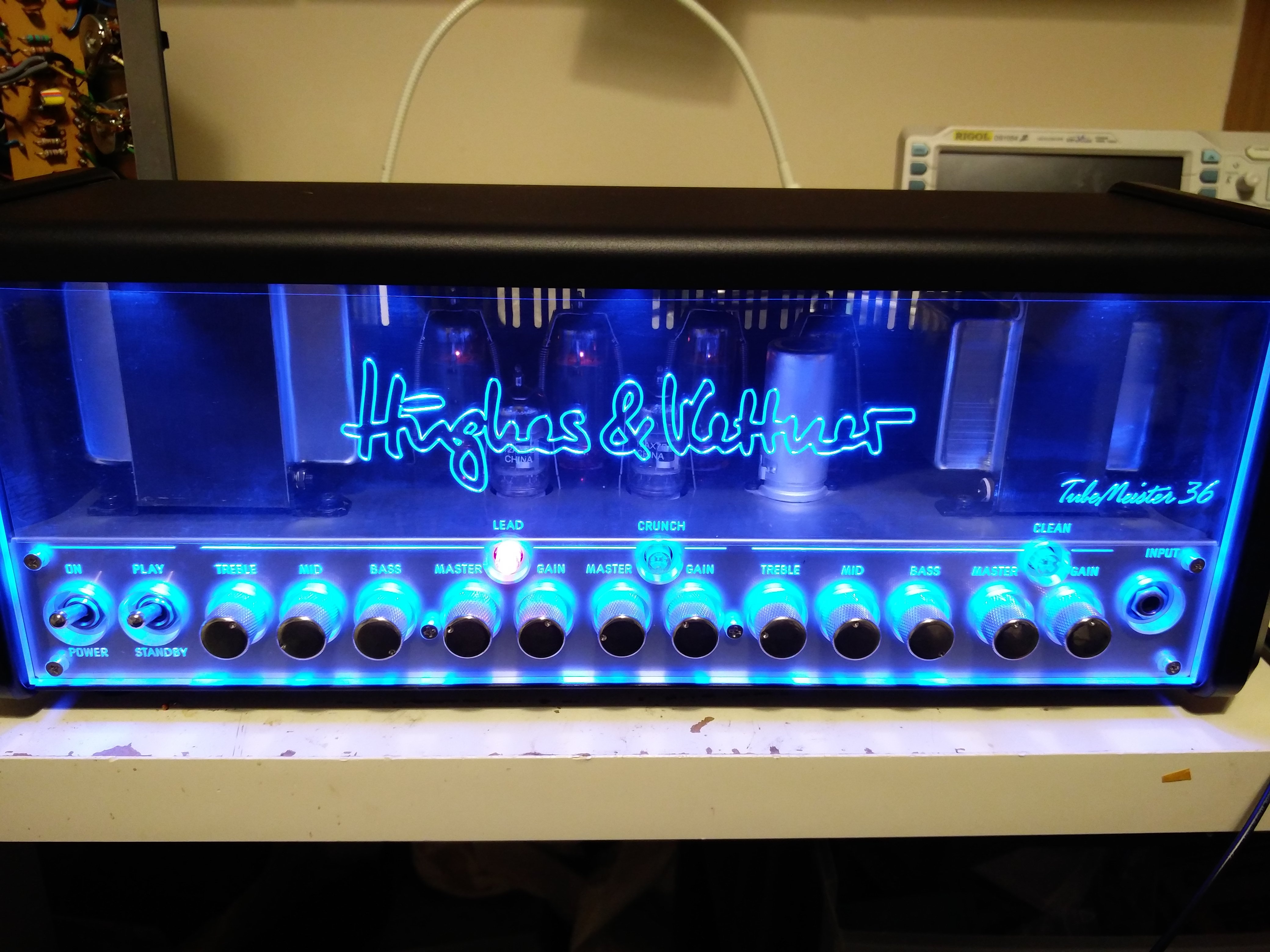
Hughes and Kettner Tubemeister repair

I’ve wanted to do a tubemeister repair since they first came out a few years back. I guess it’s a testament to general quality that this is the first to appear on the bench. I’m a big fan of the design aesthetic. 3 channels and a midi switching amp for £550ish is a lot of bang for your buck.

However, the owner was more worried about a different kind of bang – and a flash behind V1 when he flicked the standby switch. Afterwards the amp wasn’t making any sound at all.

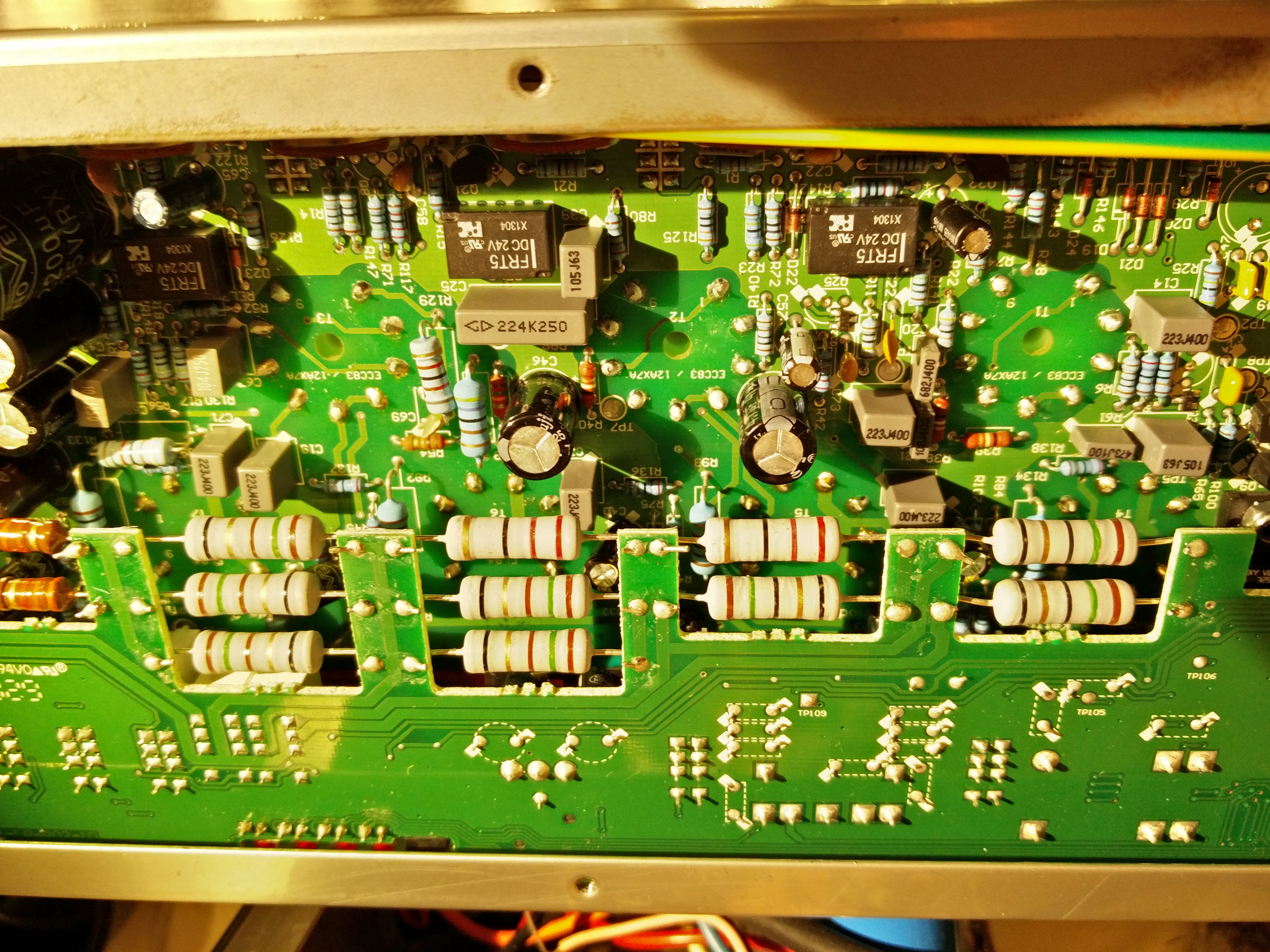
Hughes and Kettner service manuals are easily the most detailed of any of the modern manufacturers I’ve seen (honourable mention goes to Roland/Boss) but this wasn’t needed to disassemble the chassis and get back to the PCB. The chassis is all metal which reduces weight and size. There’s a bent metal lid, removable end pieces and a separate metal base.

Hughes and Kettner have a power tube management system called TSC. This checks tube balance and bias. Orange amps have a similar system (see orange amp repair). The Hughes and Kettner TSC can occasionally fail and show up an error code on the TSC lights. The parts must then be replaced with these parts. But that wasn’t necessary here.

I discovered that the HT fuse had blown, which accounts for the bang the player heard. The valves all tested good, but since the TSC turns on the power tubes using a FET in the cathode I strongly suspected the power valves. After replacing the valves and the fuse the amp came back to life!

If you have Hughes and Kettner tubemeister repair, please just drop me a message and I’ll get you up and running again.

Roland Cube Repair – Cube 80

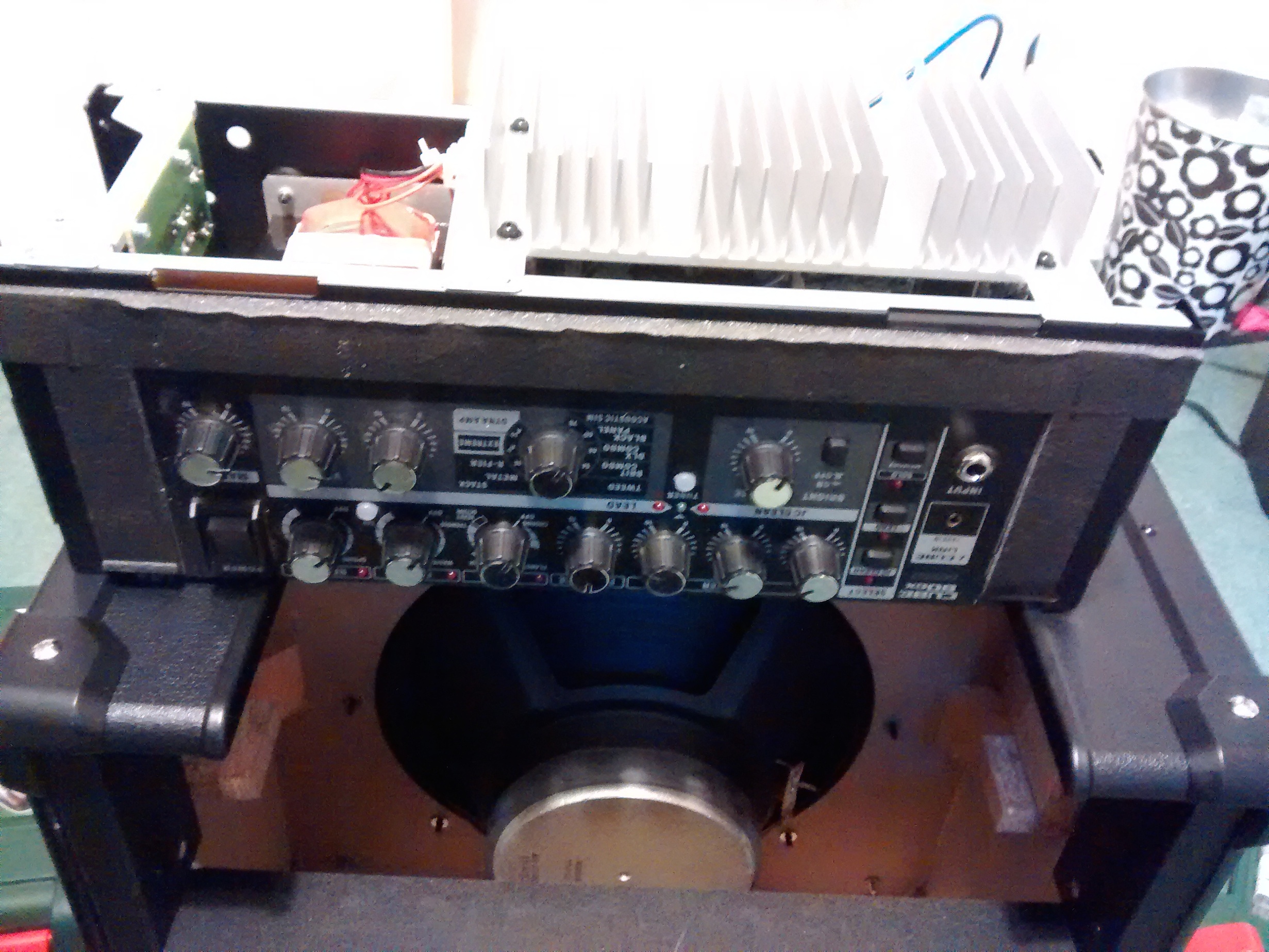
Roland Cube Repair

This Roland Cube Repair was a cube 80 from the ever popular Roland Cube range. These amps have a reputation for indestructibility and I’m not surprised. Despite their popularity and the hundreds of amp repair enquiries I receive, I’ve only ever had 3 Roland repair enquiries! Two were from the Roland Cube range, of which this is one. You’ve probably also seen the Anderton’s videos in which they set a Micro Cube on fire and shoot it at the local archery range! It survives the archery and the electronics survives the inferno (the paper speaker cone burns of course)!
Roland Cube Repair Jack Socket.jpg

But this one is not even really a faulty amp. The owner had used a cheap balanced jack as a guitar cable. Unfortunately the cable plug had disintegrated inside the amplifier, leaving a jack tip inside the input socket.

It was a relatively simple job to remove the rogue part, but I got an opportunity to admire the rigid construction of the amp whilst doing it.

If you have a Roland Cube repair you’re unusual(!), but please get in touch and I’ll get it sorted for you.