We don’t just do valve amps repairs here at Keld Ampworks. We’re just as happy with Digital modelling equipment repairs!
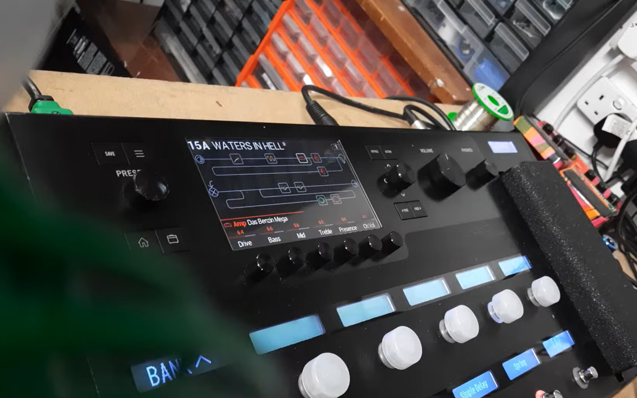
Line 6 Helix Repair – No Audio on Guitar Input
A customer recently sent in a Line 6 Helix Floor for repair after the guitar input stopped working. The unit powered up normally, all menus and controls functioned correctly, and audio passed perfectly through the auxiliary input. However, there was no signal whatsoever from the main guitar input.
The reported fault was straightforward:
No audio from the guitar input.
Auxiliary input operating normally.
Unit booted correctly with no error messages.
All other functions appeared to work as expected.
When a fault is isolated to a single input on a complex digital processor such as the Helix, the problem can lie anywhere from the analogue front-end circuitry through to the analog to digital converter to the DSP chip itself. The first step was therefore to confirm the fault and trace the signal path.
The Line 6 unit uses a clever multi level analog circuit to capture a greater dynamic range with two sepeate ADCs
Signal tracing showed that the guitar input signal was failing before reaching the converter stage.
Further investigation identified several failed capacitors in the analogue input circuit. Although these components showed no visible signs of failure, electrical testing confirmed they were no longer performing correctly, preventing the guitar signal from being coupled through the input stage.
Testing the other caps found several that were on the point of failing.
The defective capacitors were replaced with high-quality equivalents matching the original specifications. Once fitted, the guitar input immediately returned to normal operation.
The Helix was then subjected to extended testing all inputs and presets, with all inputs, outputs and switching functions verified. The repaired unit operated flawlessly throughout the test period, with both the guitar and auxiliary inputs functioning exactly as intended.
Modern digital guitar processors rely on both analogue and digital circuitry working together. While software faults are often suspected first, relatively small analogue components such as capacitors can prevent an otherwise fully functional unit from passing audio correctly.
This Line 6 Helix repair was completed at component level, avoiding the unnecessary replacement of expensive circuit boards and returning the processor to full working order.
If your processor has no signal on the guitar input, intermittent audio problems or other input-related faults, a professional Line 6 Helix repair can often restore full functionality without the expense of replacing the entire unit.
If you’ve got a Line 6 Helix repair please get in touch!
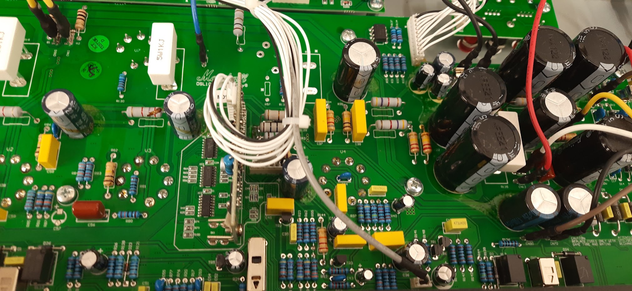
We’ve had a few questions about the ROS-2000 replacement board that I designed for the Marshall JCM 2000, so I thought it was worth putting a proper nerd level explanation together. Buckle up!
This isn’t a quick overview – it’s very much a “what we did and why” from a repair and design point of view. Buckle Up!
What the board is (and why it exists)
The ROS-2000 is a replacement for the original Marshall valve PCB, which is well known for a few issues – we mostly see them with the bias drift issue, in which a conductive board causes a thermal runaway, killing the EL34 valves.
The aim here wasn’t to reinvent the amp, just to fix the weaknesses properly and make something that’s reliable long-term.
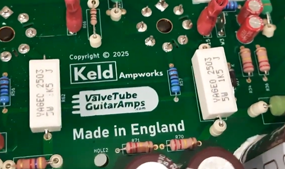
Everything was designed here at Keld Ampworks in Nottinghamshire and manufactured in the UK, rather than partially outsourced and “finished” locally. Stewart at vtga spoke to a load of UK manufacturers to select the best for the job. In the end we settled on a manufacturer in Hastings, UK (1066!) to build the main part of the board and completed the configuration here in Keld Ampworks or at Stewart’s site on the beautiful North Yorkshire coast.
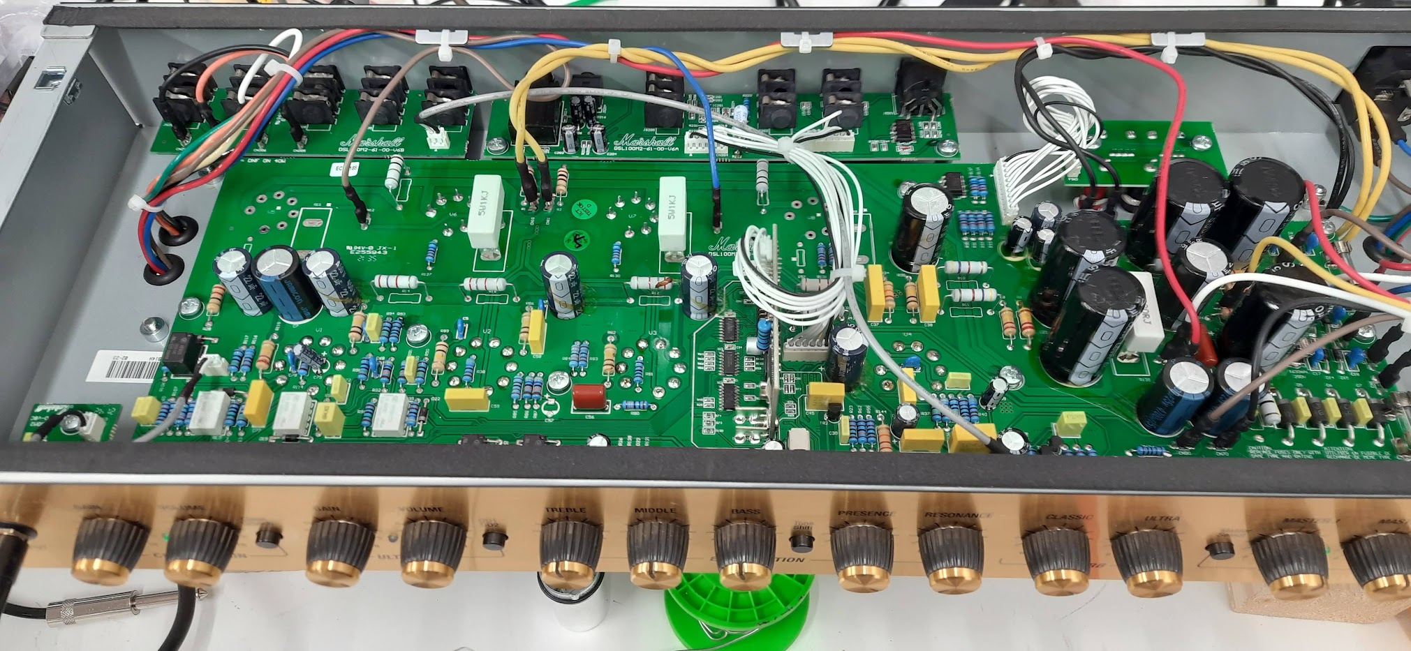
Component choices
Across the board, we’ve uprated pretty much everything:
Signal resistors are metal film (lower noise than carbon types)
High-voltage resistors are 2W rated for extra headroom
Film capacitors are Wima
Ceramics are Vishay / Murata
Electrolytics are Rubycon / Nichicon / Nippon Chemicon
Nothing exotic, just good-quality, proven parts with sensible ratings.
Whilst designing this board I noticed that there’s a capacitor in the original design that ends up reverse-biased in certain switching modes. That’s been corrected here, as it’s not something you want for long-term reliability, although I haven’t seen it cause failures!
Fixing the original fault (bias drift)
The big issue on these amps is leakage between high voltage (HT) and the bias supply.
That’s addressed in a few ways:
Physical slots cut into the PCB to increase isolation
Much greater spacing between HT and bias traces
Careful routing so the two don’t run even slightly close together
There’s also an external link used to route HT rather than crossing sensitive areas of the board.
Despite extensive design reviews we still had a nervous moment when we ran the board up for the first time, but the result was no measurable bias drift, even under quite severe heat stress testing.
Heat management
The original board uses a bridge rectifier for the heater supply, which runs hot.
That’s been replaced with four discrete diodes, spaced for airflow. They run cooler and don’t dump heat into the PCB. This issue originally caused hum noises in the clean channel on the JCM 2000 boards.
Surface Mount Components
Surface-mount tends to get a bit of a bad reputation in valve amps, so it’s probably worth addressing that directly.
They’re not used here as a cost-saving exercise – in fact our choice to use surface mount actually added cost, as we had run 2 manufacturing passes rather than a single through-hole build.
The only reason they’re used is because, in those specific parts of the circuit, they’re simply the right choice and reducing the component footprint on the switching circuit allowed us more space elsewhere to eliminate cross talk and heat disipation issues.
All of the surface-mount components are in low-voltage areas, with nothing seeing more than around 10–12V and no meaningful heat being generated. In that context, they’re perfectly reliable and allow for a cleaner layout, particularly in keeping the ground plane intact, which helps keep noise down.
Where there’s high voltage or any real power dissipation, it’s all traditional through-hole parts as you’d expect.
So it’s not a blanket approach – just using each type of component where it actually makes sense. Engineering is about using the right part for the job, not dogmatically rejecting technology based on internet nonsense! Sorry guys!
Layout and grounding
Connector positions are kept similar to the original, so installation is straightforward and doesn’t require reworking wiring looms.
On the PCB itself:
Surface-mount parts are used only where appropriate (low voltage, no heat). We
Through-hole parts are used where needed for robustness
A full ground plane is used on the underside
There’s a lot of debate about ground planes in valve amps, but in practice, done properly, they reduce noise and interference – and that’s been borne out in testing. In my previous engineering career before Keld Ampworks I spent a substantial amount of time testing audio euqipment for harsh EMC environments. Ground planes reduced interference IN EVERY SINGLE CASE. That said, inexperienced PCB designers might make mistakes with running low impedance ground panes near radiated sources to cause problems. Fortunately, we avoided that and this unit is measurably quieter than other options as a result of sensible tracking and the ground plane.
The other common complaint about valve amps is that “LEO FENDER DIDN’T USE A GROUND PLANE”. Well Leo didn’t use his amps near wifi, or wireless rigs, or lighting rigs with SMPS sources. I’ve played on stages where ’boutique’ amps have been plagued with RF interference noise whilst my own ground plane amps have stayed beautifully quiet. It’s just good engineering, folks.
Mechanical reliability
A couple of small but important details:
Raised components use ceramic spacers, so they can’t bend and short during shipping
Components are secured with non-acetone silicone, not hot glue (which goes brittle with heat)
These are the kinds of things that don’t show up immediately, but matter over time.
Other improvements
A few additional tweaks:
Screen grid resistors uprated to 1k5 to extend valve life
Flyback diodes added to protect the output transformer
Improved heater trace layout and balancing – see previous comments about understanding how to design PCBs with ground planes!
None of these change the sound in any way, but they do make the amp more robust and lower noise.
Testing
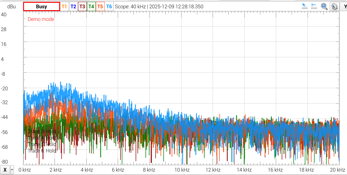
We tested the prototypes extensively to make sure that they matched up to the most recent (best) Issue 20 Marshall PCBs. The frequency responses matched up perfectly in all channels on our test TSL100 and our test DSL100. We tested it at every knob extreme and also tested the Tone shift, boost/mid boost deep and presece performance. The waveforms also matched up in clean and clipping performance. We then tested the noise and found that we had indeed managed to make the unit slightly quieter. Ground plane, folks.
Have you waded through all that? I’m impressed.
This isn’t about changing the character of the amp, it’s about making it behave properly.
The original design works, but it has some weak points. The ROS-2000 board addresses those with better layout, better parts, and a bit more attention to how things behave under real-world conditions (heat, vibration, long-term use).
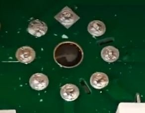
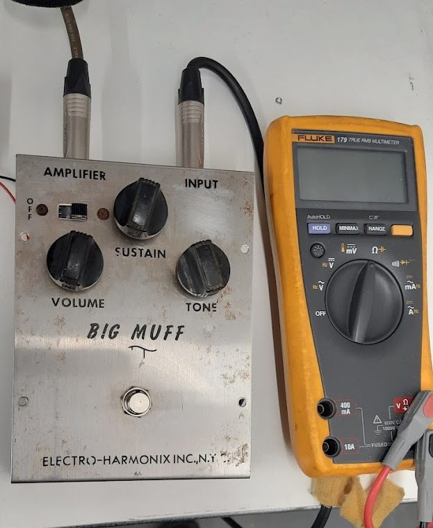
A really nice example of an early Triangle Big Muff Pi repair. From googling, I guess it is late 60s, early 70s. It came in by post from London for a 24h turnaround repair on our express service.
The owner reported weak signal, loss of volume at times, and inconsistent behaviour when engaged and tone suck in bypass mode.
Initial Inspection
The PCB showed signs of age – several dry solder joints, probably factory. A few pads were damaged or lifting, most likely from previous repairs or stress over time. Three of the five electrolytic capacitors were leaking on test. All were replaced.
A quick check of the components also revealed a 150Ω carbon comp resistor had drifted way out of spec – measuring over 2kΩ! That would’ve had a big impact on the tone and gain structure of the pedal.
Work Carried Out
All five electrolytic capacitors were replaced as a set. The originals were well past their best.
The out-of-spec resistor was swapped for a fresh 150Ω part – we used a modern replacement, chosen for low noise and stable performance.
Dry joints across the board were reflowed and cleaned up, and damaged PCB pads were carefully repaired to ensure good connectivity and long-term reliability.
The battery clip and switch were both replaced. The old clip was missing a connection and held on with sellotape! The switch was intermittent.
The owner asked for a true bypass mod, but didn’t want any drilling or visual changes – so no LED, and still battery-powered only. New 3PDT footswitch, but no drilling.
Testing
With everything reassembled, the pedal was powered up and tested thoroughly. Signal is now strong and stable, and the phat Muff tone is back. I tested it with some pumpkins style riffs (OK, OK I KNOW IT’S NOT AN OPAMP MUFF!!).
A really satisfying job on a classic circuit. No unnecessary mods, just careful repair and subtle upgrades to keep things running smoothly without spoiling the original vibe.
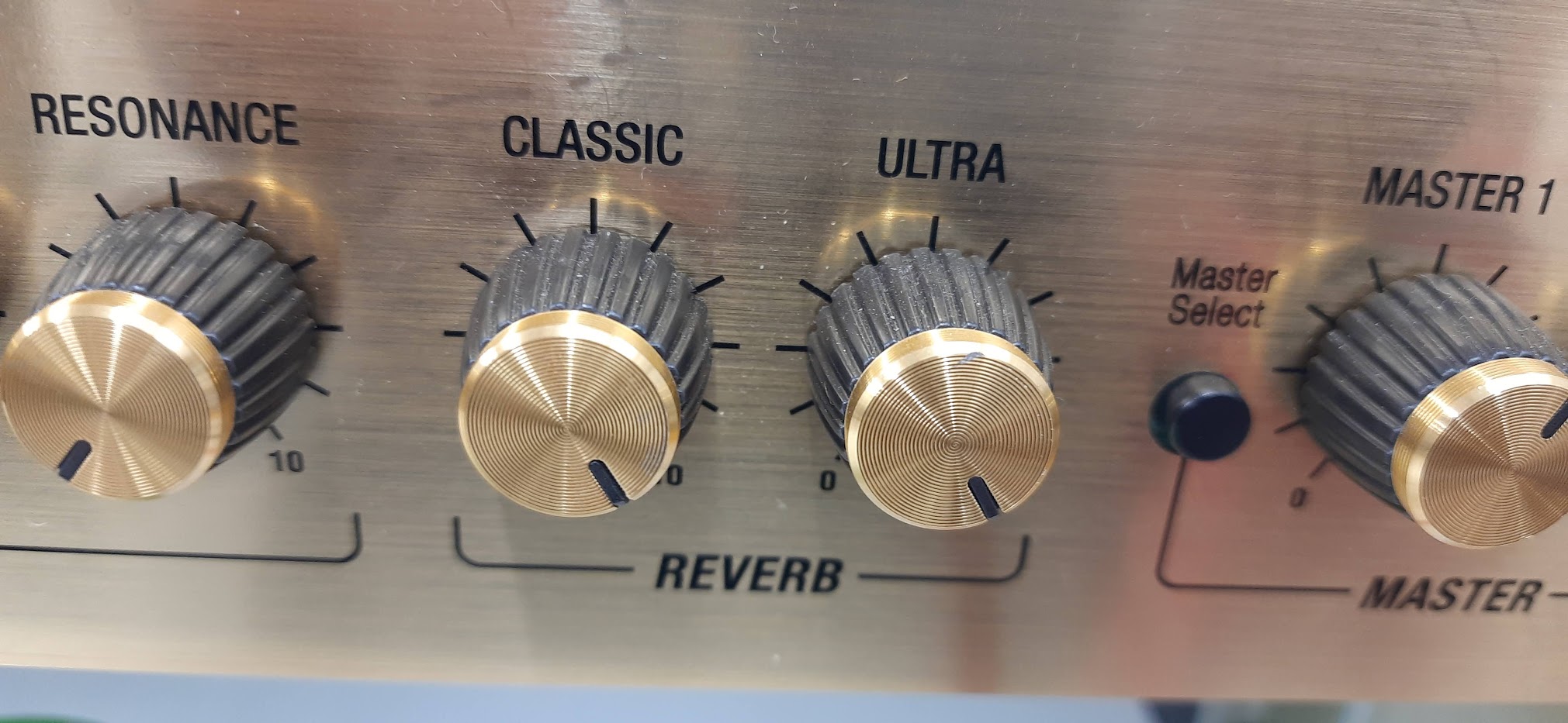
One common complaint I’ve heard from Marshall DSL40CR owners is the underwhelming reverb. To be fair, Marshall have never been famed for their lush reverb circuits – that badge tends to go to Fender or certain boutique builds – but even by Marshall standards, the DSL40CR’s reverb is particularly weak and uninspiring.
Interestingly, Marshall’s JVM series, the flagship model, delivers much more satisfying reverb tones, suggesting that the lacklustre performance in the DSL isn’t down to DSP limitations, but more likely a result of how the reverb is mixed into the signal path.
I’d had a few customers mention this in passing, but recently someone brought in their DSL40CR specifically asking if I could engineer a proper fix. After studying the signal flow and DSP mix arrangement, I found the culprit – and the solution turned out to be surprisingly straightforward.
Inside the amp, there’s a resistor that sets the mix level between the dry signal and the DSP-generated reverb. From the factory, this resistor is a 6.8kΩ (6k8) unit. That value results in a very low contribution from the reverb path, hence the barely-there effect.
By swapping this resistor for a 2.2kΩ (2k2), the reverb signal is allowed to mix more strongly with the dry path, leading to a much more useful reverb tone. After testing and A/B’ing the results, the customer was really pleased – it brought the reverb into much more usable territory without overdoing it or introducing unwanted noise.
A Word of Caution
This modification requires surface-mount soldering (SMD) skills – not something to be attempted with a basic iron and a shaky hand. The resistor in question is a small SMD type, and damaging the PCB while trying to replace it could leave you with a very expensive paperweight. So unless you’re confident working at that level, please don’t try this at home.
Want This Fix?
If you’ve got a DSL40CR and find the reverb lacking, I can include this mod as part of a standard DSL40CR service – it’s a quick, elegant solution that makes a real difference. If you’ve got a competent local amp tech, there’s enough information here for them to work it out. But again: if any of this seems unclear, don’t experiment on your amp – it’s not worth the risk.
Feel free to get in touch if you’d like the mod done properly.
I don’t often see a DSL40CR come through with this kind of erratic behaviour – it was one of those jobs that kept me scratching my head until the real root cause showed itself.
The Symptoms (as described by the customer)
The amp would unpredictably switch from the Clean channel into Overdrive (OD) without touching the footswitch or front panel. I noticed that putting the amp in standby would instanly trigger the fault
Otherwise, it sounded fine: the valves were healthy, the output stage appeared to behave, and no obvious catastrophic faults were present.
Removing a valve changes the power supply behaviour, so that’s where I started.
What I found was subtle: the control supply (low voltage rail) was not rock solid. The rail that feeds the preamp switching logic and control electronics was sagging or shifting, just enough so that under certain conditions the amp would interpret it as a switch command.
Once the control rail wobbled or dipped, the channel logic would misbehave and flip the amp into OD mode. A surprising symptom, but less surprising once you realize how sensitive those digital / switching circuits can be when their supply is out of spec.
I’m lucky enough to have a friend who knows the technical issues with this range of amps better than literally everyone else in the world. He suggested I look at the power supply section on the rear board as this is the most prone to sagging.
In addition, during the inspection I noted a few design / build quirks that I’ve occasionally encountered in the DSL40CR family (and in other Marshall amps), which may be part of why these amps sometimes exhibit low output or noise issues:
Low power / reduced volume: I’ve seen DSL40CRs (and sibling models) drift into low power mode, often caused by conductive glue traces (flux residue or glue meant for mechanical stability) creeping between printed traces, forming parasitic leakage paths. These “hidden conductive paths” can robs bias or collapse gain subtly, especially under heat.
Noise issues from 1 M grid resistors: Some of those 1 M grid or grid‑stop resistors in the preamp are notorious for turning noisy over time, especially when they drift in value or have internal contamination. That adds hiss or crackle, especially on the quieter parts of the circuit.
Shorting via ceramic resistor bodies: I’ve even found situations where the body of a ceramic resistor is so close to a high voltage (HV) board trace that it arcs or shorts under certain conditions – e.g. if the resistor’s coating is cracked, or there’s flux residue, or simply vibration has shifted things. That can cause weird intermittent behaviour, grounding, or leakage between circuits.
So, while the main symptom in this unit was the channel‑switching, it was wise (and necessary) to check for all these known weak spots in the DSL40CR line.
After these repairs, the DSM40CR stayed rock solid in each channel: no more phantom switching. I ran the amp through its full range of channels, settings, footswitch tests, power cycling, and warm-up cycles. Then I subjected it to a soak test at gigging levels for a good hour or two – it remained stable, no drift, no switching anomalies.
I also measured output power and bias and compared it to spec – it was right in the expected ballpark (i.e. no low‑power symptoms). That confirmed that the power stages and bias were healthy.
If you have a DSL40CR (or any Marshall) behaving oddly – randomly jumping channels, volume sagging, noise creeping in – don’t assume the worst (i.e. bad valves). A disciplined service + power‑supply / control circuit check is often all that’s needed to bring it back to life. Please do get in touch
Recently, I had the pleasure of completing a WEM Copicat tape echo repair on three different units, each presenting its own challenges. After years of use, they often require some TLC.
All three Copicats needed new tape loops, which are essential for achieving that classic echo effect. Additionally, extensive mains safety work was necessary to ensure safe operation. During the inspection, I discovered visibly leaking electrolytic capacitors in each unit, which I promptly replaced to prevent further damage.
One of the Copicats had a stiff arm that affected playback, so I carefully adjusted it for smoother operation. Another unit was extremely noisy, indicating potential issues with the tape mechanism; after thorough cleaning and adjustments, the noise was eliminated. Finally, one Copicat had a faulty channel 2, which I diagnosed and repaired to restore full functionality.
After completing these WEM Copicat tape echo repairs, each unit was tested and sounded fantastic, ready to deliver that iconic echo sound once again. If your tape echo needs some attention, don’t hesitate to reach out for a WEM Copicat tape echo repair!
I recently repaired a Hughes & Kettner Switchblade amp that had a shorted mains transformer, causing power failure. Thankfully, I sourced a replacement transformer from a genuine parts supplier, ensuring top quality for the repair.
After installing the new transformer, I performed a full service, which included cleaning key components and checking all connections. I also replaced the old output valves with a new pair of EL34s to restore the amp operation.
Following the Hughes & Kettner Switchblade amp repair, I tested the amp at various volumes, and it delivered as expected. The owner was thrilled to have their amp back, ready for upcoming gigs.
Recently, I had the pleasure of repairing an AER Compact 60 amp that was experiencing frustrating audio dropouts. The owner had noticed that sound inconsistently faded in and out during performances, which can be a nightmare for any musician.
To diagnose the issue, I conducted a soak test—a method that involves running the amp at gigging volumes for an extended period. This technique helps reveal intermittent faults in the AER Compact that might not be evident during a brief test. During the AER Compact repair I monitored the amp, it became clear that the dropouts were linked to oxidized switches. These switches, often overlooked, can degrade over time, leading to poor connections and sound cut-offs.
After cleaning the affected switches and ensuring all connections were secure, I re-tested the amp. The result of the AER Compact Repair? A solid, consistent output with no further dropouts. The owner was thrilled to have their AER Compact 60 back in perfect working order, ready for the next gig.
Here’s a fix for a Line 6 Helix related ground loop problem I did for a customer a couple of years ago. He used the HX floor unit to control the amp channel switching and it created a really bad ground loop hum. It appears that the HX amp control sleeve is ground referenced, which is a pity on such an amazing unit.
You could modify a TRS cable to break the ground loop and it would work fine. On bigger stages though so the better is to build an adapter box to break the connection so that any length TRS cable can be used.
This isn’t a particularly common problem for Helix users, but it’s a real one that people occasionally come across.
The ground loop is caused by both pieces of gear. There’s a ground path running through the audio path of the amp and helix and a ground path running through the switching path of the amp and helix.
In some amps, the ground scheme will be such that noise is induced into sensitive parts of the audio path. The guitar amp designers won’t have paid much attention to this because most guitar amps with these sockets were designed before the advent of systems that share audio and switching functions, like Helix or GigRig. The amp designers were only expecting the user to plug in a latching footswitch to the jack. Latching footswitches don’t share an audio ground so no loop is created, so the designers didn’t need to control the ground currents. Thus the amplitude of the induced noise is determined by the amp grounding scheme resulting in different amps exhibiting the problem at different levels. Hope that makes sense.
It couldn’t happen if the Helix sleeve wasn’t grounded, it wouldn’t happen if the amp’s FX connector sleeve wasn’t grounded.
The opportunity to break the ground connection entirely is only available at the Helix or switcher end. Whilst an isolated footswitch design could be built in at the amp’s end, this would be awkward because it would require an industry standardised LV power source in switching systems to power a relay (or opto) in the amp. Worse, it would stop the footswitch socket working with the very common stand alone latching footswitches (which have no power). No manufacturer is ever going to choose to do that. However it’s very easy to create a relay driver at the Helix end so that the sleeve is isolated from the audio ground (much like the GigRig remote switch options).
The noise level is also proportional to the amount of external noise as this is the external noise source that’s then picked up by the GND loop. In my workshop there’s plenty of external noise sources, just like in lots of venues. Studios, should hopefully be much quieter.
Unfortunately an ISO hum silencer box can’t fix it because this needs to respond to DC changes – the transformers in an ISO hum silencer will block DC. You could use one of those in the audio path to fix the problem by a different route (break the loop in the audio instead of the switching), but then that potentially messes with the audio path, so it’s not the best solution.
Above is a picture of the box I built for my customer. Very simple to make if you’ve got a soldering iron and a step drill. You can build one up yourself from the picture, or if anyone ever wants one building I can make one up at my usual labour rate.
Here’s the BOM to make your own: Hammond 1590A style box. Switchcraft 12B stereo metal jack socket Neutrik NMJ6HCS or NMJ3HF-S or similar stereo plastic bodied socket 2 wires!
This Seymour Duncan Powerstage repair was a pretty simple job and was turned around next day for the customer on my express service. The customer was an American pop punk band, currently touring the UK.
Though he normally used a step down converter. Unfortunately the customer had inadvertently connected his 110V seymour duncan powerstage to UK mains (nominally 230V, really 240V) and it had blown up spectacularly.
The part that was blown up is a hifi poweramp, made by a subsidiary of Bang And Olufsen. They’re used in many amps nowadays, including Gallien Kruger, Acoustic Image, Fender Bassman 500 and Fender Tonemaster.
Ironically, the unit has an internal selection for 110V/230V to allow the unit to be swapped very quickly between UK and US mains. I’m not giving details of what to do online as encouraging people to meddle with mains electricity is beyond the scope of this blog!
The band’s tour manager brought the unit in for repair and I got the new power amp module delivered on next day shipping.
I set the Powerstage back to 110V operation for the customer as had a spare for UK gigs but were touring US again immediately on their return.
If you have a Seymour Duncan Powerstage 170 that you need repairing, please do drop me a message.