
Marshall JCM 2000 – ROS-2000 board design overview
We’ve had a few questions about the ROS-2000 replacement board that I designed for the Marshall JCM 2000, so I thought it was worth putting a proper nerd level explanation together. Buckle up!
The project was a collaboration with Stewart at www.valvetubeguitaramps.com and it’s available exclusively from his website at the following link ROS-2000 PCB for JCM2000 Amplifiers – Valve Tube Guitar Amps
This isn’t a quick overview – it’s very much a “what we did and why” from a repair and design point of view. Buckle Up!
What the board is (and why it exists)
The ROS-2000 is a replacement for the original Marshall valve PCB, which is well known for a few issues – we mostly see them with the bias drift issue, in which a conductive board causes a thermal runaway, killing the EL34 valves.
The aim here wasn’t to reinvent the amp, just to fix the weaknesses properly and make something that’s reliable long-term.
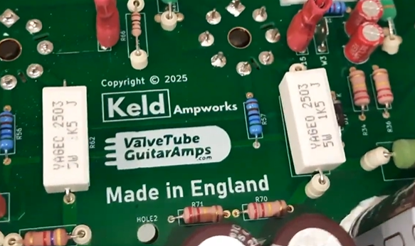
Everything was designed here at Keld Ampworks in Nottinghamshire and manufactured in the UK, rather than partially outsourced and “finished” locally. Stewart at vtga spoke to a load of UK manufacturers to select the best for the job. In the end we settled on a manufacturer in Hastings, UK (1066!) to build the main part of the board and completed the configuration here in Keld Ampworks or at Stewart’s site on the beautiful North Yorkshire coast.
Component choices
Across the board, we’ve uprated pretty much everything:
- Signal resistors are metal film (lower noise than carbon types)
- High-voltage resistors are 2W rated for extra headroom
- Film capacitors are Wima
- Ceramics are Vishay / Murata
- Electrolytics are Rubycon / Nichicon / Nippon Chemicon
Nothing exotic, just good-quality, proven parts with sensible ratings.
Whilst designing this board I noticed that there’s a capacitor in the original design that ends up reverse-biased in certain switching modes. That’s been corrected here, as it’s not something you want for long-term reliability, although I haven’t seen it cause failures!
Fixing the original fault (bias drift)
The big issue on these amps is leakage between high voltage (HT) and the bias supply.
That’s addressed in a few ways:
- Physical slots cut into the PCB to increase isolation
- Much greater spacing between HT and bias traces
- Careful routing so the two don’t run even slightly close together
There’s also an external link used to route HT rather than crossing sensitive areas of the board.
Despite extensive design reviews we still had a nervous moment when we ran the board up for the first time, but the result was no measurable bias drift, even under quite severe heat stress testing.
Heat management
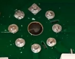
The original board uses a bridge rectifier for the heater supply, which runs hot.
That’s been replaced with four discrete diodes, spaced for airflow.
They run cooler and don’t dump heat into the PCB. This issue originally caused hum noises in the clean channel on the JCM 2000 boards.
Surface Mount Components
Surface-mount tends to get a bit of a bad reputation in valve amps, so it’s probably worth addressing that directly.
They’re not used here as a cost-saving exercise – in fact our choice to use surface mount actually added cost, as we had run 2 manufacturing passes rather than a single through-hole build.
The only reason they’re used is because, in those specific parts of the circuit, they’re simply the right choice and reducing the component footprint on the switching circuit allowed us more space elsewhere to eliminate cross talk and heat disipation issues.
All of the surface-mount components are in low-voltage areas, with nothing seeing more than around 10–12V and no meaningful heat being generated. In that context, they’re perfectly reliable and allow for a cleaner layout, particularly in keeping the ground plane intact, which helps keep noise down.
Where there’s high voltage or any real power dissipation, it’s all traditional through-hole parts as you’d expect.
So it’s not a blanket approach – just using each type of component where it actually makes sense. Engineering is about using the right part for the job, not dogmatically rejecting technology based on internet nonsense! Sorry guys!
Layout and grounding
Connector positions are kept similar to the original, so installation is straightforward and doesn’t require reworking wiring looms.
On the PCB itself:
- Surface-mount parts are used only where appropriate (low voltage, no heat). We
- Through-hole parts are used where needed for robustness
- A full ground plane is used on the underside
There’s a lot of debate about ground planes in valve amps, but in practice, done properly, they reduce noise and interference – and that’s been borne out in testing. In my previous engineering career before Keld Ampworks I spent a substantial amount of time testing audio euqipment for harsh EMC environments. Ground planes reduced interference IN EVERY SINGLE CASE. That said, inexperienced PCB designers might make mistakes with running low impedance ground panes near radiated sources to cause problems. Fortunately, we avoided that and this unit is measurably quieter than other options as a result of sensible tracking and the ground plane.
The other common complaint about valve amps is that “LEO FENDER DIDN’T USE A GROUND PLANE”. Well Leo didn’t use his amps near wifi, or wireless rigs, or lighting rigs with SMPS sources. I’ve played on stages where ’boutique’ amps have been plagued with RF interference noise whilst my own ground plane amps have stayed beautifully quiet. It’s just good engineering, folks.
Mechanical reliability
A couple of small but important details:
- Raised components use ceramic spacers, so they can’t bend and short during shipping
- Components are secured with non-acetone silicone, not hot glue (which goes brittle with heat)
These are the kinds of things that don’t show up immediately, but matter over time.
Other improvements
A few additional tweaks:
- Screen grid resistors uprated to 1k5 to extend valve life
- Flyback diodes added to protect the output transformer
- Improved heater trace layout and balancing – see previous comments about understanding how to design PCBs with ground planes!
None of these change the sound in any way, but they do make the amp more robust and lower noise.
Testing
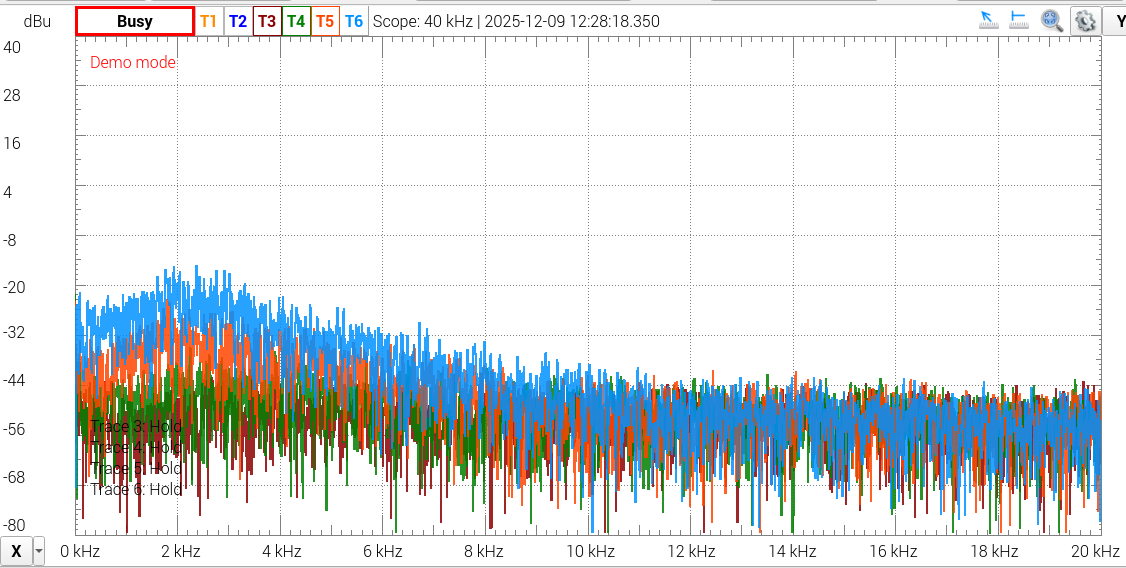
We tested the prototypes extensively to make sure that they matched up to the most recent (best) Issue 20 Marshall PCBs. The frequency responses matched up perfectly in all channels on our test TSL100 and our test DSL100. We tested it at every knob extreme and also tested the Tone shift, boost/mid boost deep and presece performance. The waveforms also matched up in clean and clipping performance. We then tested the noise and found that we had indeed managed to make the unit slightly quieter. Ground plane, folks.
Have you waded through all that? I’m impressed.
This isn’t about changing the character of the amp, it’s about making it behave properly.
The original design works, but it has some weak points. The ROS-2000 board addresses those with better layout, better parts, and a bit more attention to how things behave under real-world conditions (heat, vibration, long-term use).
Hope that was useful, if you like what you see, please do head on over to Stewart’s website here: ROS-2000 PCB for JCM2000 Amplifiers – Valve Tube Guitar Amps
If anything’s unclear or you’ve got specific questions about the design, feel free to ask.