This JCM900 repair arrived after the owner found that it was lacking in volume.
It’s a 2009 unit, two channel, with a 2203 type circuit on channel A and a higher gain circuit on channel B.
The problem appears to have been with the amplifier bias. Although the valves were matched, the bias on this JCM900 repair was set very high. The bias set the dissipation at about 95% – Marshall suggest about 70%. This causes the output to compress much earlier than would otherwise occur. Fortunately this is easy to fix.
I then offered to soak test the amp which is a means of testing the amp in the conditions it would be in rehearsal or gig. This is great for revealing those hard to find problems that would otherwise missed. It revealed a minor fault with the preamp – a crackle appeared behind the note transients. Since this was a relatively minor problem, the owner chose not to have it looked into.
I sometimes have been known to complain that some amp manufacturers give little thought to ease of repair – mesa boogie have had some stick from me in other reports. Some marshall repairs – thinking the DSL range in particular – are a bit difficult because of their complexity but this JCM900 repair is a delight to work on. They’ve really thought things through both in terms of reliability and ease of repair. It’s probably the easiest channel switching amp to repair that I’ve seen.
Although the channel A had a great plexi type tone, the owner isn’t a big fan of the Drive sound in ChannelB – he’s thinking of modding the amp to acheive the fabled Silver Jubilee tone so stay tuned – this one might turn up again.
If you have a JCM900 repair, please do get in touch.
Now, is it good things or bad things that come in threes? It must be good things. This was the third of three vintage vox ac30 repairs that came to me over a few weeks in summer 2015. Vintage amps have a particular smell and when there are 3 vintage vox amps in the workshop for repair you soon become very used to it!
This amp is probably the toughest repair job that I’ve worked on over the last 6 years. Another repair company in Lincolnshire, experienced with vintage amp repairs, had looked at the amp but had ultimately had to give up. I don’t really blame them.
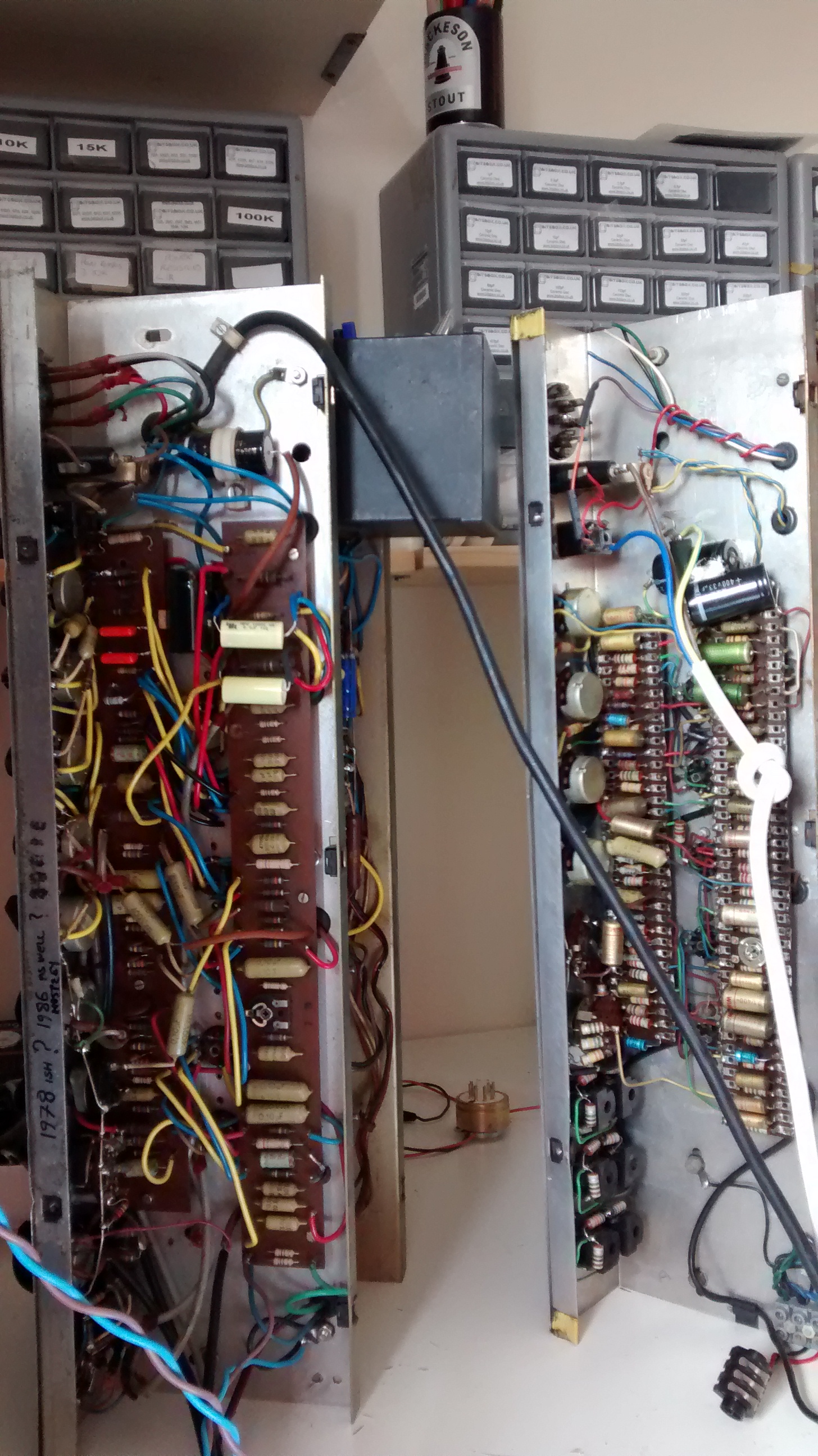
This vintage Vox AC30 (there’s a picture of it on the 1961 vox page too) is I think a 1970s model. I’ve estimated it at 1973, with substantial modifications through the years. However, I’m an electronics geek, not an amp history geek, so I may be wrong. Someone who’s opened up the amp in the past has written “1978 ish ? 1986 as well, mostly ?” inside it. I judge it to be 1973 because the vox logo is a traditional VOX logo as used in the 60’s, but this could have been swapped during it’s lifetime. Early 1970s vintage Vox AC30s used PCBs too. STragely, this doesn’t look like any of the 70’s PCBs that I could find. So, the jury’s out on this one!
Some 70s vintage Vox AC30s came with reverb circuits, but this amp uses a solid state reverb circuit that I can’t find any record of in 70s amps. You can tell that the amp didn’t ever have a valve reverb because it’s a 10 valve unit. The ’78 reverb unit used 11 valves with the extra triode used to buffer the signal into the spring reverb and to make up gain after it. But the amp had a reverb market on the front panel, I assume this must have been fitted later.
I’ve spoken before of the peculiarities of doing amp repairs on guitar amps and other electronics is that the actual process of repairing can take just 5 minutes, but the fault replication and diagnostic period is often much much longer. This problem is made worse in situations when the problem disappears intermittently. This one would disappear as the amp warmed up, after 20min or so.
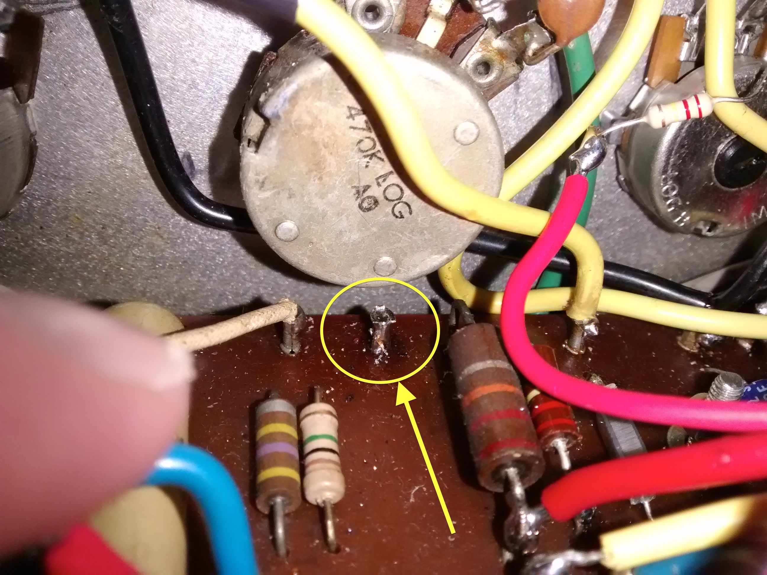
The fault turned out to be a loose turret connection between the normal preamp volume control and the phase inverter. The connection appeared to be physically intact with a good solder joint. Grounding the point through the pot appeared to have no effect. However when removing this turret it broke in two. There must have been solder holding the piece together, but not making a reliable connection.
After that was fixed, we decided to wire out the solid state reverb unit and return the unit to vintage AC30 spec by adding back in the LoGain input on the vintage channel. While doing this I noticed that someone who’d worked on the amp, probably whoever fitted the reverb had wired up the input jack wrongly, leaving the brilliant channel jack socket with a high resistance to ground at all times. This turned the unit into a pickup point and the amp was feeding back on its own at high treble settings, with no guitar plugged in. Nightmare! Anyway this was soon fixed.
When finished, this is easily one of the nicest sounding amps I’ve ever played. I love the way the Vintage Vox AC30 circuit distorts. It’s easy to see why it’s become a popular circuit for the likes of Dr Z, Trainwreck, Matchless, Bruno etc. to copy. You can see a bit of it in the quick video I did to celebrate it’s finish!
This vintage vox AC30 repair took a good deal of effort, and I was the second repairer to work on it, bit I’m glad to say that it is now fixed. If b you have a vintage vox AC30 and it’s in need of a bit of TLC, please so contact me via the contact page.
Shortly after the Confetti 1962 vintage ac30 repair arrived, this vintage Vox repair turned up on my bench too! The 1961 in the picture is on the right, the left amp is a 1970’s vintage vox, which you can read about here.
This is (as far as I can tell) a 1961 model. It was once covered in a cream vinyl, but the customer (who had it from new!) had decided at some point that it would look cooler in black and painted it.(!)
After laying down his axe many years ago, the customer decided to sell the amp and brought it to me to service.
I found that the brilliant channel didn’t work. This turned out to be an out of tolerance resistor in the gain stage and a faulty coupling capacitor. Also the tremelo system wasn’t working. In vintage vox circuits, this consists of 6 triodes worth of analog electronics. 2 are an audio input buffer, 2 create a modulating signal and 2 mix the modulation with the audio signal. The fault was with the modulation circuitry and was again down to a worn out capacitor. This is not an uncommon task in vintage Vox repairs.
As with the Confetti 1962 vintage ac30 repair, I hard wired the mains to 245V for UK operation and replaced the ancient power cord with a modern tri rated mains lead.
I’m pleased to say that the customer was very happy with the vintage vox repair! If you have a Vintage ac30, or a vintage amp in need of repair, please get in touch.
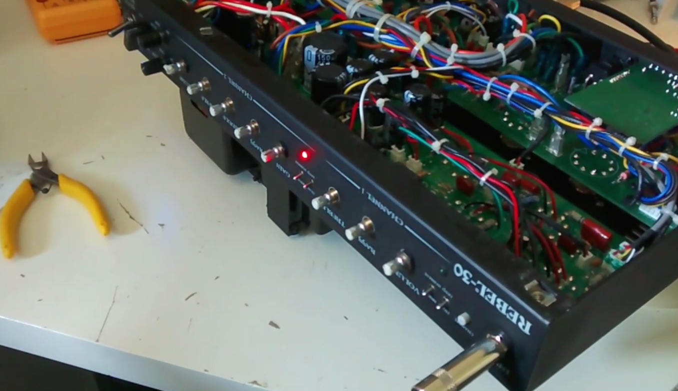
This amp is a Rebel 30 by Egnater. At first, I had a bit of trouble with the Egnater repair but I’m pleased to say that I found a solution for the customer. The diagnosis itself didn’t prove a problem, the problem was simply the gain potentiometer itself. This is a dual ganged part (2 pots in one). One half of the pot behaved fine, the other half was open circuit in the first part of the turn. This caused a loud clunk at the point where the track re-appears (see the video).
There was no maker’s mark on the pot so I couldn’t be sure what brand it was: probably a far eastern part sourced by the contract manufacturers. It’s quite easy to find dual ganged 500K pots from guitar gear suppliers but they’re designed to fit inside guitars or in ’boutique’ hand wired amps – none of them will fit in to the space in this tiny Egnater repair.
Of course I tried to contact Egnater, but received no reply. Unfortunately I wasn’t been able to find an alternative panel mount part that will fit into the space constraints inside the case. There are switches and capacitors internally that would prevent the available chassis mount parts from being suitable.
However I came up with a fix that sorts some of the issues with the existing pot. There is still a small bit of silence for the first part of the turn, but the very loud bang is mostly gone, with only a whisper remaining, inaudible unless you’re listening for it. The sound returns whilst the channel is still within the ‘clean’, not yet crunchy part of the drive channel turn, so all the useful elements of the gain channel remain.
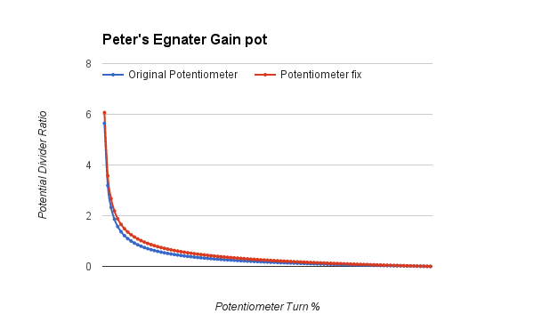
Mathematically, the fix I’ve employed affects the potentiometer ratio only very slightly (as in the graph), I’d argue imperceptibly. The truth is it’s probably even closer than the theory suggests, as real pots don’t curve this smoothly! I’ve done a video comparing the tone before and after the mod, to demonstrate that there’s no real difference, but who knows, you may pick up a nuance. As you can hear, the bang is very evident in the video before the mod, but inaudible after.
The video appears here:
I’m pleased to say that the customer was very happy with the Egnater repair! If you have a Rebel 30, or another Egnater in need of repair, please get in touch.
This Blackstar repair was a simple valve amp service before the amplifier was sold. The amp is a series 1-45 2×12 combo. It’s a fantastic 2 channel amp with 4 modes, bright Clean, warm clean, Crunch and Super Crunch.
The amplifier uses Blackstar’s DPR and ISF patents, you can read more about Blackstar’s DPR on my valve amp attenuators page.
The amplifier was performing well, but a test on the valve tester turned up two faulty preamp valves which were replaced. The week before, I’d had another Blackstar amp repair, but as they’re a fairly new brand, I don’t get many Blackstar repairs!
Blackstar amps are one of the many types that I repair, please get in touch if you need my help.
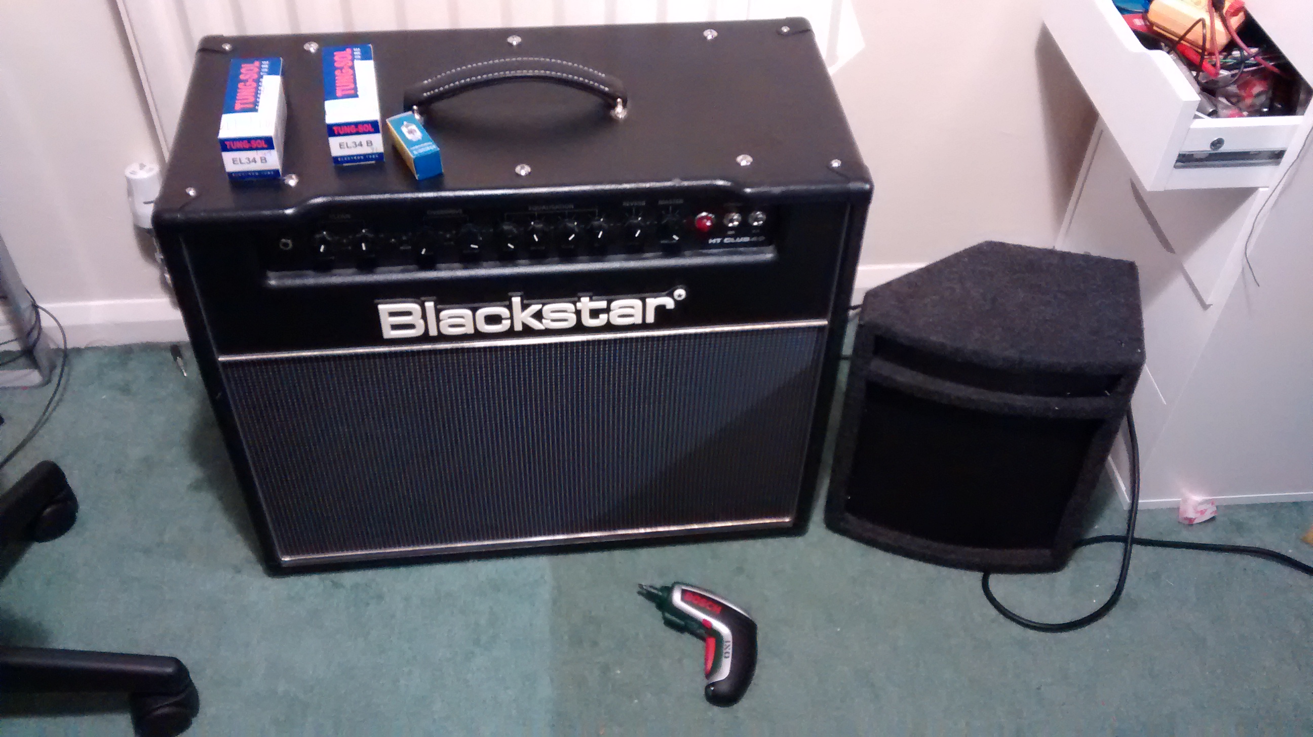
Recently, a Blackstar amp repair was brought to my workshop in Newark. The amp was an HT40 (the Club 40 combo) in working condition, but the owner wanted to try a new set of EL34 power valves in the amp. He selected a matched pair of Tung Sol with slightly higher gain (according to my valve tester) than then outgoing stock Ruby parts.
However, whilst checking the amp over my valve tester highlighted a fault in one of the Sovtek preamp valves, so I’ve replaced this with a JJ ECC83S.
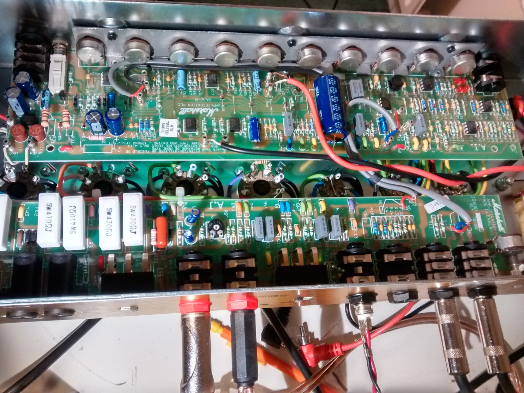
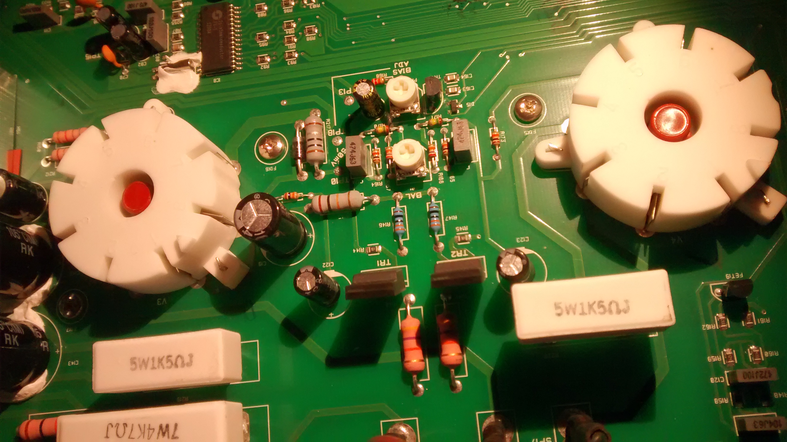
There’s an interesting and fairly unusual element in these Blackstar HT amps – they appear to use a transistor Phase inverter (you can see it in the image at the top), so all the 4 gain stages in the 2 12AX7 preamps are used purely for gain in the preamp circuit. They sound great. This unit doesn’t use the DPR circuit that I mention on that page.
Anyone who knows me as a player, rather than a tech will know I’m a bit of a Blackstar amp fan. I play a Blackstar Series 1 50W head (recently upgraded from a heavy Blackstar Series 1 45 combo). I almost bought one of the these HT40s actually!
If you have a blackstar repair, please get in touch!
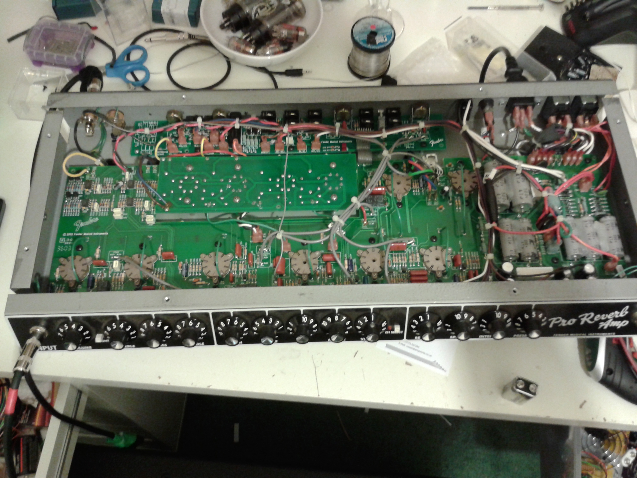
A customer brought this fender repair to me with a common complaint. The valve amp was blowing a fuse every time the standby switch was turned on. A valve amp blowing fuses can be a number of things, but in this case I suspected that the amp probably had a faulty power valve.
This turned out to be true. One of the 6L6 valves had a fault that causes a high current to pass between anode and cathode causing the fuse to blow.
This can occur in all valve amps with all types of valve. Elsewhere on this blog, there’s a Marshall valve amp blowing fuses that was down to a shorting EL34 valve. There’s also a more recent mesa boogie valve amp blowing fuses.
Once a power valve is replaced, it must be rebiased. I set this fender back to manufacturers spec. Matching power valves should always be used.
If you have a valve amp blowing fuses, please do Contact me for advice.
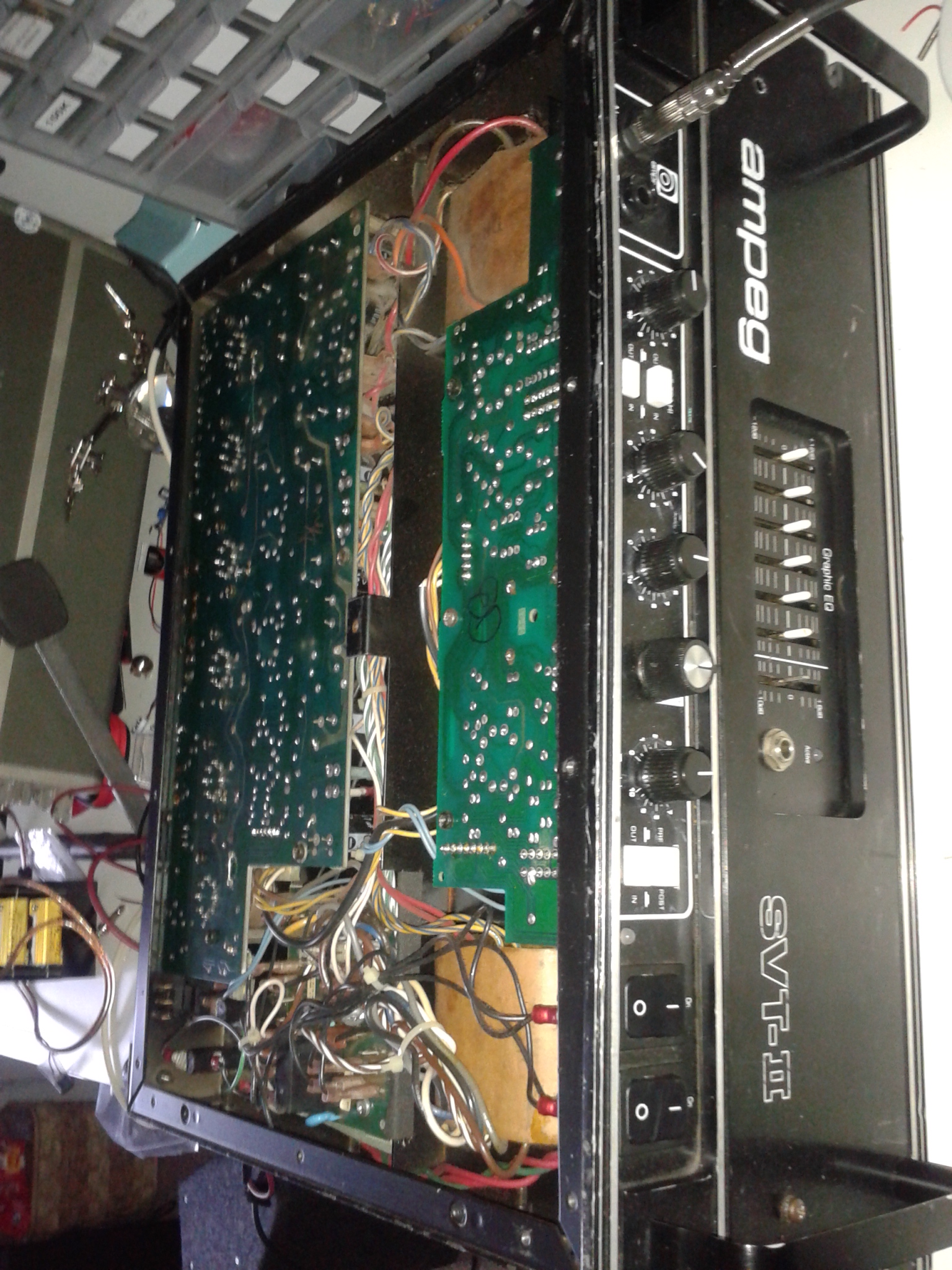
What a huge beast this Ampeg repair is! Weighing in at an incredibly heavy 32kg I wasn’t sure that my workbench would take the strain!
It’s an SVT ii powered by 6 KT88 output valves meaning two massive transformers, owner for three mains and one for the output stage. When both must be capable of 300W continuous, that’s a lot of iron!
The owner was finding that the amp would drop in volume after a few minutes of running. It’s a common problem that I was quickly able to trace back to an oxidation issue, meaning a nice low cost repair for the customer.
If you have an Ampeg repair that needs attention, please get in touch , but you’re carrying it in!
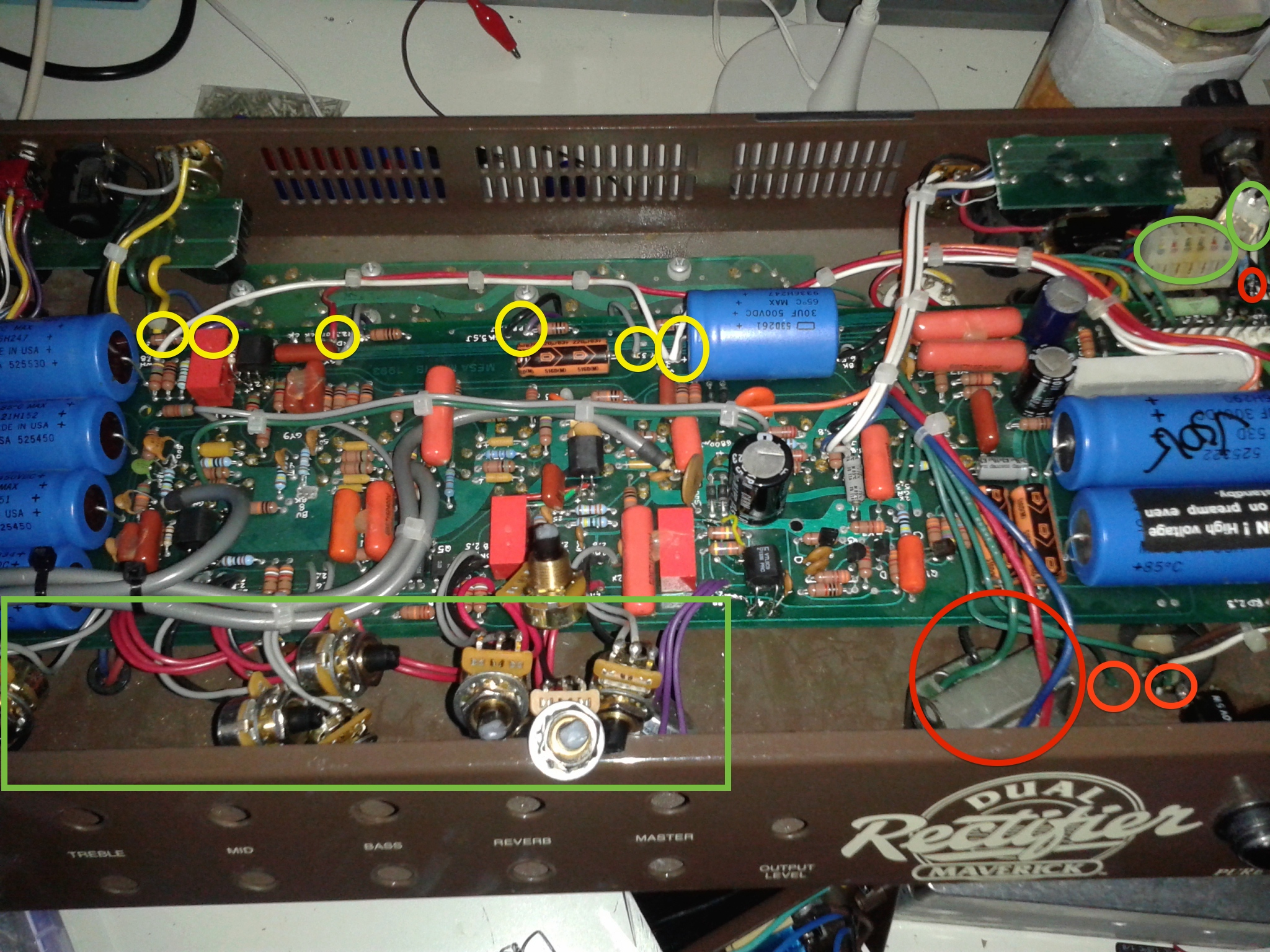
This Mesa Boogie repair was one of the nicest amps to play, but one of the longest repairs of the year I’m afraid!
In this case, the Maverick had a problem with the channel switching. After a few minutes the rhythm channel would increase in volume, and the lead channel would bleed through an unpleasant fuzzy distortion. The fault was fixed by the opto-isolator replacement in the switching circuit.
It’s never a good thing to discover that your amp is faulty, but a broken amp is particularly bad news for owners of Mesa Boogie amplifiers. This is because Mesa Boogie construct their amplifiers in a way that lengthens the repair time.
The reason is that the amplifier is soldered into position on all four sides. Any changes to the board must be done after completely dismantling the amp (taking 30minutes each time). If several things are replaced in a more complex job, then the costs quickly mount up. Before I add to any myths, it’s NOT because the amplifier is PCB, it’s perfectly possible to make a PCB amp that’s easy to repair! It’s also possible to make a Point to Point amp that’s a nightmare to repair as well – I’ve seen them!
I get quite a lot of the JCM2000 series in for repair – both DSL and TSL. I think it’s because they were so popular, rather than any endemic issues. This particular JCM2000 is a TSL100, the triple super lead model.
I’m writing the blog post quite a while after the repair now, so I’m looking at my notes to remember the issue. IIRC, the amp needed new valves and the owner mistakenly paired valves 1+2, 3+4, instead of the correct 1+4, 2+3. He knew how to bias his own amp and knew about pairing valves, but had always replaced for a matched quad in the past. When he paired the valves wrongly things had become hot and smokey – the valves red-plated For more information on valve amp bias, check my bias FAQ.
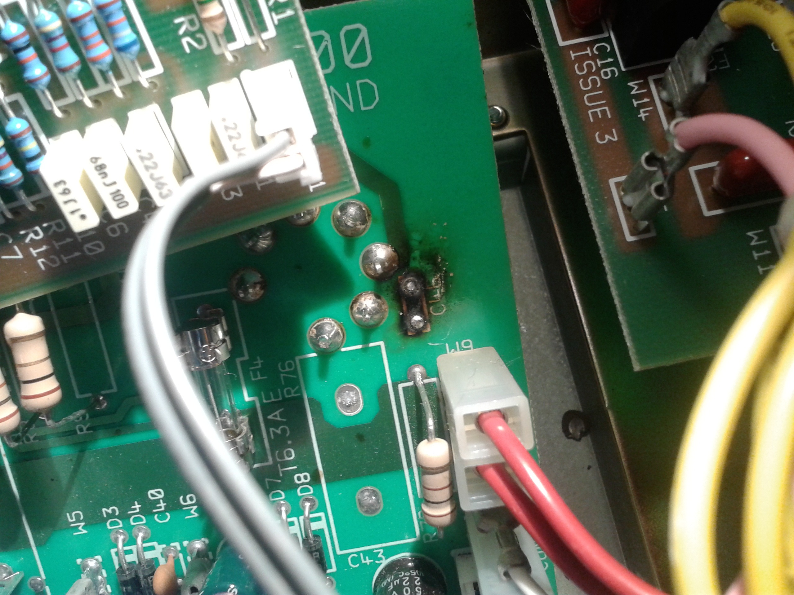
The amp had become so hot that a screen grid resistor (R78) – mounted upside down in the amp – had melted its solder connection and fallen out of the amp, melting some cabling where it landed. I replaced this resistor (with a lighter weight, but equally rated component). I also replaced the burned out suppression capacitor that can be seen in the picture.
The lesson to be learned: read my bias FAQ before replacing power valves yourself. If in doubt, ask!