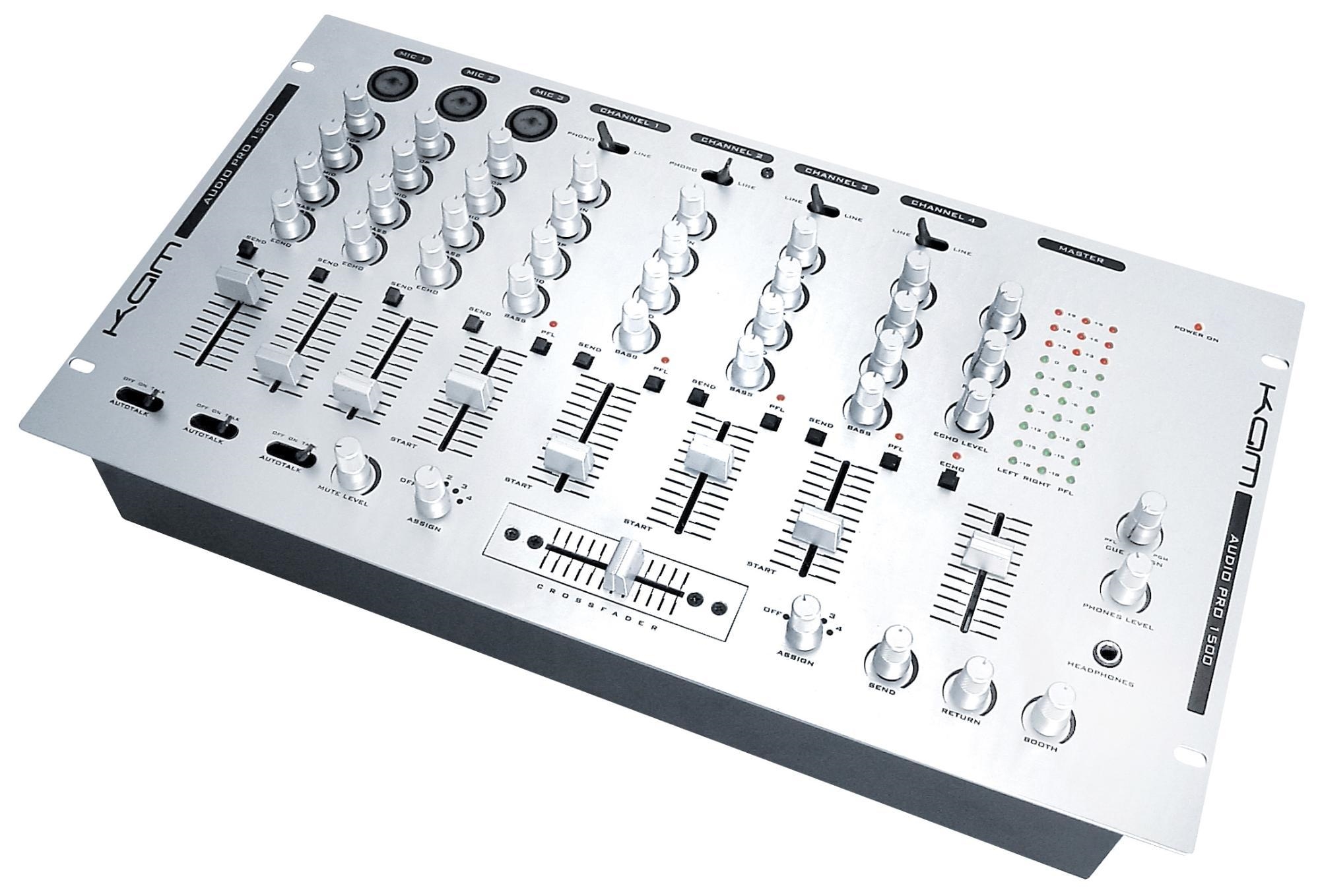
Carvin repair – Nomad 

Carvin repair

This Carvin repair was completed for Simmonds music in Grantham. They received the amp in part exchange. The amp would occasionally drop to very low volume, with no apparent reason.

From the beginning it was obvious that the Carvin repair had been attempted by another tech in the amplifier’s past. The first valve stage had sustained some damage. Unfortunately it appeared that some damage had remained unfixed.

The amp also had a bad problem with a hum on the high gain channel which I was able to fix.

After replacing the plate resistors, the DC heater circuit, the cathode bypass caps and as number of other smaller parts, the amp was completed and returned to Simmonds in as-new condition with an Ampworks guarantee transferable to the new owner.

If you have a Carvin repair, please do contact me and I’ll get it working again!

Presonus Monitor Station Repair – Loud Buzz!

presonus-monitor-station-repair

This presonus monitor station repair was posted to me by a customer who’d read my report on another presonus repair. The original unit exhibited a constant buzz and the customer reported similar problems here. Upon testing the unit, the problems I experienced on testing the unit were less severe, fortunately the experience with the previous Presonus Monitor Station repair led me to go straight for the power supply section of the circuitry and I noticed the same area of internal circuitry was showing signs of damage. The repair was completed within the first hour, keeping the costs low for the customer.

As you can see in the video below, it’s working well now!

Update June 2023: I’m now selling a capacitor kit, so you can fix your presonus yourself. More info here

If you have a presonus monitor station repair, please get in touch, I’m getting quite used to them!

BOBBIB7 – GR55 GK Pin7 break out box/break in box

BIBBOB GK GR55 pin7 break out board

There’s only a niche interest in this one, so I’ll keep it brief. It’s a break in box and break in box for pin 7 on a roland synth system. Catchily named BOBBIB7.

UPDATE 2017: This is now for sale at RSD Sound.

This is a PCB I designed for use with GR55 and similar guitar synth pedals and GK equipped guitars, such as Godin, Brian Moore, Fender Roland-Ready Strats etc.

I’m going to assume that if you’re reading this you know what a GR55 is and what a GK guitar cable is.

The 13 pin GK cable’s pinout can be found here.Roland GK 13pin pinout

You can see on John’s page that the normal magnetic guitar signal is found on pin7, so accessing this pin with ‘normal’ jacks is useful. This board has 3 functions, detailed below.

GK cable Break out box:

The GR55’s guitar out socket is quite noisy, too noisy for use with high gain amps. This is due to the large number of switcheroos (technical term) inside the GR55 pedal demodulating and getting onto the audio signal.

To avoid this, many users (including me, up to now) run the magnetic signal down a normal lead and the GK signal down a GK lead. By plugging a GK cable into the BOBBIB7 GKinput, and a jack into the output, you can tap off the magnetic tone without it ever entering the pedal. You must also have the GK output connected to a GR55 because the GK pickup buffers your mag signal in order to send it down the GK cable and so requires GR55 power.

GR55 Break in box:

This is the best bit. By plugging a normal guitar into the jack input and a GK cable into the to GK output you can use any guitar with the modelling awesomeness of the GR55. I use the GR55 as a ‘second amp’ when playing live and I’ve wanted to do this for ages, so I can do gigs with any guitar and not just my GK ones. Also useful if you’ve got a string breaking problem on your GK guitar. The board has space for a little amplifier to amplify the mag guitar signal, providing the LoZ source that the GR55 will expect. It uses a single SMT FET and a handful of 0805 passive components.

GR55 as a multiFX pedal:

I haven’t tried this yet, but it should work fine. By plugging an FX send into the jack input and an FX return into the GR55 mono output you can use the various FX channels of the GR55 with any normal setup. Darned useful. EDIT (April ’16): I have now tried and gigged this setup in the FX loop of my amp. It does indeed work very well! I ran the Patch Level between 100-130 and the volume knob at about 11 o’clock.

BIBBOB7 Schematic:

Nothing to it really. BIBBOB GK GR55 pin7 break out board


More info:

  • 1.6mm FR4
  • Purple solder resist, which sounds better.
  • Gold Plated pads and through plating.
  • 2 sided board, through hole plated
  • Board designed to fit into a musikding.de B type box, which is their version of the Hammond 1590B
  • Runs from the GK 7-0-7 supply, no batteries or PSU needed.
  • I couldn’t find the jacks that fit the board at my local supplier (farnell UK) so I’ve wired them floating as in the pic.

Select between mag on a GK guitar and a mag only guitar

I’ve been asked about adding a switch to select p7 input between mag thru GK cable and mag from jack. This can be done with a few simple mods. Badly scanned scribbles here.

However, you could actually use the board with two jacks as originally and install a cheap passive AB or ABY switcher box. This would select between the mag-only straight from the guitar and the break-out jack of the BOBBIB. The output would go to the break-in jack, through the buffer and to the GK. Obviously there’s no real use for the “Y” mode here. Here’s a video of the idea in action:

Disclaimer:

I cannot be held responsible for any loss, personal injury or damage to equipment resulting from the use/misuse of the BOBBIB7 or information on this page.

Available:

This is now for sale at RSD Sound. When out of stock at RSD Sound, I will build to order.

http://www.vguitarforums.com/smf/index.php?topic=15383.msg109823


Egnater Repair – Rebel30

Egnater-repair-rebel30

This amp is a Rebel 30 by Egnater. At first, I had a bit of trouble with the Egnater repair but I’m pleased to say that I found a solution for the customer. The diagnosis itself didn’t prove a problem, the problem was simply the gain potentiometer itself. This is a dual ganged part (2 pots in one). One half of the pot behaved fine, the other half was open circuit in the first part of the turn. This caused a loud clunk at the point where the track re-appears (see the video).

There was no maker’s mark on the pot so I couldn’t be sure what brand it was: probably a far eastern part sourced by the contract manufacturers. It’s quite easy to find dual ganged 500K pots from guitar gear suppliers but they’re designed to fit inside guitars or in ’boutique’ hand wired amps – none of them will fit in to the space in this tiny Egnater repair.

Of course I tried to contact Egnater, but received no reply. Unfortunately I wasn’t been able to find an alternative panel mount part that will fit into the space constraints inside the case. There are switches and capacitors internally that would prevent the available chassis mount parts from being suitable.

However I came up with a fix that sorts some of the issues with the existing pot. There is still a small bit of silence for the first part of the turn, but the very loud bang is mostly gone, with only a whisper remaining, inaudible unless you’re listening for it. The sound returns whilst the channel is still within the ‘clean’, not yet crunchy part of the drive channel turn, so all the useful elements of the gain channel remain.
Egnater-pot-repair
Mathematically, the fix I’ve employed affects the potentiometer ratio only very slightly (as in the graph), I’d argue imperceptibly. The truth is it’s probably even closer than the theory suggests, as real pots don’t curve this smoothly! I’ve done a video comparing the tone before and after the mod, to demonstrate that there’s no real difference, but who knows, you may pick up a nuance. As you can hear, the bang is very evident in the video before the mod, but inaudible after.

The video appears here:

I’m pleased to say that the customer was very happy with the Egnater repair! If you have a Rebel 30, or another Egnater in need of repair, please get in touch.

Blackstar amp Repair – Series 1-45

Blackstar amp repair

This Blackstar repair was a simple valve amp service before the amplifier was sold. The amp is a series 1-45 2×12 combo. It’s a fantastic 2 channel amp with 4 modes, bright Clean, warm clean, Crunch and Super Crunch.

The amplifier uses Blackstar’s DPR and ISF patents, you can read more about Blackstar’s DPR on my valve amp attenuators page.

The amplifier was performing well, but a test on the valve tester turned up two faulty preamp valves which were replaced. The week before, I’d had another Blackstar amp repair, but as they’re a fairly new brand, I don’t get many Blackstar repairs!

Blackstar amps are one of the many types that I repair, please get in touch if you need my help.

Orange Tiny Terror Modification – BS watch! – Ampworks, Newark

Below is an extract from an email conversation with a customer who asked for some impartial advice on a popular ‘mod’. I’ve redacted names, images and product links. I’ve no wish to slander anyone or their products, but I do hope to bring some clarity in a field awash with mis-information. All opinions are my own, if you disagree with something, please do let me know, preferably in a civil manner! Please view this a general piece of advice regarding amp modification, rather than a specific commentary upon this product.

BS stands for ‘bad science’. If you thought otherwise then my apologies, OK? 🙂

Hi Mike,I’ve just commented on the various claims, referencing these photos. There’s a few interesting potential benefits, […] I’ve gone into quite a bit of detail, so I might pop this on my blog so others can find it. 🙂

My modification rule of thumb is that anything that makes less difference than a new set of guitar strings is pointless. I’d say there are two component changes here that may pass that criteria. Firstly, the bias mod will make a noticeable difference, that you may or may not like. If the designer used C7 to shape the amp’s tone, which is likely from the component position, then removing C7 will bring the biggest tonal change to the whole amp. The boutique components are probably BS. 🙁

[image removed, the following italic text is pasted from the seller’s description, my comments are in colour]

CLAIM: Swapping the valves for a full set of new JJ Electronic ECC83S and EL84

AMPWORKS COMMENT: New valves can of course make a difference, you can try this yourself by buying new valves from a reputable supplier (such as me!) Valve changes generally make less difference than a new set of strings. 🙂


CLAIM: The cheap push-on heater connectors were dropping too much voltage between the transformer heater wiring and the V3 heater pins.

COMMENT: Probably BS. It’s feasible that the connector contact resistance may drop voltage and hard wired connections are more reliable, but the sensible approach is to replace only if a valve heater actually stops working (maybe after contact oxidation from storage in a damp garage). This will have no effect upon sound.


CLAIM: The rubbish heater connectors are removed and the valve heater circuit wiring is completely hard wired. Wire dress was particularly poor.

COMMENT: This means that the heater connections (yellow and black in the photo) weren’t tightly twisted at the factory. Heaters can be a source of hum, twisting the wires reduces the magnetic field created by the high current in the wires. If you have a problem with hum (with no guitar plugged in) then this is useful. If no hum problem, no point!


CLAIM: Bias was set too high. Output tube bias is corrected to produce maximum power output.

COMMENT: OK, this is not BS. The tiny terror is cathode biased (meaning it self biases (see my blog page on bias here). But the designers have chosen to set this self bias point quite hot. Because valves are non linear this does make a difference to the sound the amp produces. Whether it’s a change you’ll like is another question. The output stage will be louder and cleaner. You’ll hear the difference more if you play it pretty loud.


CLAIM: Preamp voltages were OK in 15W mode, but a bit on the low side in 7W mode.

COMMENT: Probably BS. This means nothing without context. There’s no such thing as an ‘OK’ or a ‘bad’ preamp voltage, unless the valve is pushed outside of it’s performance limits.


CLAIM: Components were ordinary commercial grade, nothing special. Critical components in the signal path are upgraded to boutique grade items, including:

  • Mallory 150M Series capacitors, silver mica capacitors

  •  COMMENT: Someday I’ll do a proper scientific comparison of the ’boutique’ cap brands, I’ll try and remember to let you know, I personally  suspect that any change will be very VERY subtle. 🙂 What’s MUCH more interesting is that on his photographs he’s actually removed C7 completely. This is likely to have a MUCH MUCH bigger effect than any brand change. C7 is between the guitar input and the first valve. It looks like that cap was originally connected in series so removing it will change the low end response (assuming the frequency corner was previously set to over 80ish Hz).
  • carbon composition resistors, for a more authentic vintage valve sound.

  • COMMENT: This is an interesting topic investigated quite thoroughly by RG Keen here. . His conclusions show that there may be some extra distortion created by these resistors that guitarists like. However they have to be used properly, not just replaced as a matter of course. RG recommends that they be replaced every few years as they may become unreliable when used in this way. Carbon comp resistors are generally noisier (hissy) than metal film equivalents.

MXR Carbon Copy Repair

Carbon-copy-repair

I’ve talked elsewhere (here and here) about Carbon copy repairs and the ESD issue that causes the problem. I’m just going to take a moment to discuss the symptoms that show the problem in the carbon copy pedal.

As I understand it, this issue has been fixed in new production units so if you’re buying, don’t let it spoil your enjoyment of a great little delay unit.

The issue is with the switching circuit. Mxr use a circuit related to the millennium bypass. This is a true bypass circuit that uses clever circuitry to operateb the LED without using a chunky and unreliable 3PDT SWITCH.

If you see a carbon copy that works in bypass mode but doesn’t switch in the effect or illuminate the effect LED then the carbon copy had fallen full of the ESD problem. The modulation LED will probably still work.

I use the same method as the service engineers at MXR in the USA to fix this issue. I replace the faulty components and across each of fit a special component that blocks transient voltages such those caused by static buildup. As I see a lot of these, I’ve started to keep stock of a carbon copy ESD fix kit. The components are less than 2mm wide so it takes an experienced hand to fit them.

UPDATE: 2017

The MXR ESD repair kit is now available for sale at www.rsdsound.co.uk. If you’re an experienced repairer and skilled with SMT repairs then you can purchase this kit. If in doubt, just post it to me and I’ll sort it for you.

http://www.rsdsound.co.uk/product/mxr-carbon-copy-esd-repair-kit/

If you have a carbon copy repair for me, please get in touch. You can drop the pedal in, or post it to me.

Silent Single Coil

Cancelling electromagnetic interference on a single coil guitar.

Status: Ongoing
Started: May 2012.
Edited: October 2014
Edited: May 2016

Sound Clips

Here’s a quick video of the test coil after it was fixed to my Godin.

Summary

A device can be created that replaces the backplate of a strat style guitar. This consists of a large noise picking coil that is placed in series between the guitar’s pickups and signal ground. The electrical properties of this coil are such that it does not affect the sound of the instrument.

Objective:

  • Create a device that cancels out or mitigates hum interference from audio frequency EM sources
  • Device does not change the tone of the instrument.
  • Device is a reversible modification to an instrument.
  • Device is significantly cheaper than the commercially available offering.

Pos

Bill Of Materials

Build Instructions – May 2016

  1. Create a loop coil former of the desired size and shape. I used small picture hanging nails hammered into a bit of softwood and angled them outwards to trap the wires against the wood.
  2. Secure the starting end of the wire to a spare nail and solder a stranded insulated wire to the end (7/0.2 is fine).
  3. Wind the loop wire around the former. 200 turns recommended. If using the recommended wire you will have to join wires reels together at more than one point. Use heatshrink.
  4. Secure the finishing end end of the wire to a spare nail and solder a stranded insulated wire to the end (7/0.2 is fine).
  5. Use small pieces of insulation tape to wrap the coil.
  6. Affix to the back of the guitar using a method of your choosing

Background:

In April 2012 I played guitar in the pit for a production of The Full Monty at the Palace Theatre in Mansfield. The show being largely funk based, I took along a guitar with single coils (SCs). SC hum has never been the biggest issue for me, but like many theatres the palace theatre is fitted with an induction loop system. The SCs picked up the loop signal (which of course contained my guitar sound from a PA feed) and horrible feedback ensued. I finished the week’s run of shows using the pickups only in RWRP mode to cancel the interference.

Let me be clear: I’m not against loop systems(I admit to bias in their favour!). It’s down to the musician to sort the problem so here we go…

Possible Solutions:

  • Humbucker. A four conductor humbucker can be wired in parallel. Certainly cancels hum, gives a sound something like a single coil, but not entirely!
  • Stacked Humbucker as offered by Seymour Duncan and DiMarzio. These are reported to work well and give a better single coil approximation, but by necessity, they reduce the size of the ‘wanted signal’ magnets and thus change the characteristics of the pickup.
  • Backplate cancellation loop (marketed as Suhr BPSCC or Ilitch BPNCS). Ideal, but the commercial options are not wallet friendly. Ideal for a pro who can afford the £300+ Suhr price tag to complement a £2000 Suhr guitar, but not an option for me or other semi-pros and ‘weekend warriors’. Also, these products aren’t compatible with strats with reverse polarity middle pickups (such as mine). Edit September 2014: Lindy Fralin prices now down to $200.

Chosen Solution:

A cost effective DIY implementation of the backplate cancellation loop will be the discussion of this page along with a proposal for a tweak to allow usage with RP middle pickups.

Note: This experiment makes use of information from US patent 7259318B2 filed by Ilitch S Chiliachki on Aug 27th 2007, although the idea of hum cancellation in guitar dates back to Seth Lover in the 50’s and magnetic field cancellation loops are regularly used in other fields. I don’t claim it as my own work. To the best of my knowledge I do not infringe any of the inventor’s rights by disseminating the information below. It is not my intention to make these for profit. Suhr and Lindy Fralin offer systems licensed from the inventor.
 

  1. If desired, you could wax pot the large noise picking coil to eliminate the risk of microphonics. Discussion of this procedure can be found elsewhere. CAUTION: Do not attempt to wax pot the large coil unless you are sure you can do it safely.

Theory Summary

The  large noise picking coil is wound with thicker wire than the signal picking coil. This reduces the resistance of the coil. It also has fewer turns and no core, this reduces the coil’s inductance. The bridge pickup of my strat has a DC resistance of just over 6K. Say we use 200 turns on an example 20×20 cm loop using the 36AWG wire listed above. The wire needed would be 160m long. Since it has a resistivity of 0.987ohms/metre the total resistance would be 157.92 ohms.I haven’t measured the inductance of my pickups, I’d guess at about 1-3Henries, where the noise pickup coil will be more in the milliHenries range. Because of the large difference in magnitude, it is assumed that RDC(signal coil) ~= RDC(signal coil + noise coil) and ZL(signal coil) ~= ZL(signal coil + noise coil).

Related Experiments

Could the coil be implemented as a thin track on a PCB? First instincts say that to lower the resistivity enough of the track it would have to be made thicker which might end up with an unmanageable size of backplate.

Behringer DC9 Observations

Behringer DC9 Frequency Response

This pedal is based on the MXR Dyna Comp, much like the Ross Comp, Keeley Comp, and others. The pedal uses an OTA, the LM13700 to limit the signal. For an in depth look at how an OTA based compressor works, see R.G. Keen’s www.geofex.com.

Mine’s a niche use for this pedal – and I may attempt a different solution and try this in my guitar rig instead – I currently use an ‘Edward the Compressor’ by Marshall (another OTA!). I imagine most people landing on this page will be looking for guitar info, for which I hope it will be of interest. Bear in mind that i use a LoZ output for these tests if you’re driving straight from a guitar.

I wanted to know what I’d have to do to use this as a limiting circuit to protect the user of a set of IEMs. For my application, a signal from the Desk is fed into input the limiter circuit. A headphone amp then provides the current to drive the headphones.

I need:

  1. High compression ratio, say <20:1 – a hard limiter
  2. Large dynamic range
  3. A fairly flat response inside and outside compression, say <+/-3dB
  4. It’s useful to have an indicator of when compression is active – not a common thing in guitar pedals


For a DC9 schematic, see Behringer_DC9 drawn by ‘lubeto’ on freestompboxes. Hope you don’t mind me posting your work here ‘lubeto’!

For the below responses, Output Level Control was set to 50%. The generator has an OpZ of 50R and the receiver an input Z of 100k.

The first graph is a level sweep with a 1kHz sine wave with the sustain control set at the two extremes and at a midpoint. The circuit is indeed a hard limiter rather than a compression in the ‘studio’ sense of the word. Increasing the sustain control moves the trace to the left, resulting in compression for smaller signals.

Behringer DC9 Compression Characteristics

I also saw that say that THD was about 2% at 330mVRMS input, 5% at 560mVRMS and 10% at 1VRMS for all traces. This means that the main source of distortion was unrelated to the position of the sustain control. I imagine T5 is to blame here.

The second graph is a frequency response graph at the same three 3 sustain control positions. A 10mVRMS input signal was used for the uncompressed signal and a 100mVRMS for compressed signals. It can be seen that the frequency response in compression has an increase in bass frequencies, whereas the uncompressed response has a treble emphasis.Behringer DC9 Frequency Response

  1. The DC9 appears to fit point 1 for me, the compression ratio is better than 20:1
  2. With the sustain control at 100%, the range between compression onset and 2% THD is about 20mV to 330mV – about 24dB, which is pretty good.
  3. There’s about a 6dB bass hump at 100Hz in compression and a 5dB treble hump out of compression. This is not very flat!
  4. Point 4 could be addressed, but since lower voltage at the COMP BIAS results in the reduction in gain(compression), I can’t simply buffer the signal here and drive an LED. I’d use a comparator type circuit.

I probably won’t be using this for my IEM solution, but since it was only £8 on ebay, it’s not the end of the world! It will probably find its way onto my pedal board.

Test data is here:


Hope somebody finds this information useful! Bear in mind that Use it at your own risk and for your own enjoyment.