

This pedal is based on the MXR Dyna Comp, much like the Ross Comp, Keeley Comp, and others. The pedal uses an OTA, the LM13700 to limit the signal. For an in depth look at how an OTA based compressor works, see R.G. Keen’s www.geofex.com.
Mine’s a niche use for this pedal – and I may attempt a different solution and try this in my guitar rig instead – I currently use an ‘Edward the Compressor’ by Marshall (another OTA!). I imagine most people landing on this page will be looking for guitar info, for which I hope it will be of interest. Bear in mind that i use a LoZ output for these tests if you’re driving straight from a guitar.
I wanted to know what I’d have to do to use this as a limiting circuit to protect the user of a set of IEMs. For my application, a signal from the Desk is fed into input the limiter circuit. A headphone amp then provides the current to drive the headphones.
I need:
- High compression ratio, say <20:1 – a hard limiter
- Large dynamic range
- A fairly flat response inside and outside compression, say <+/-3dB
- It’s useful to have an indicator of when compression is active – not a common thing in guitar pedals
For a DC9 schematic, see Behringer_DC9 drawn by ‘lubeto’ on freestompboxes. Hope you don’t mind me posting your work here ‘lubeto’!
For the below responses, Output Level Control was set to 50%. The generator has an OpZ of 50R and the receiver an input Z of 100k.
The first graph is a level sweep with a 1kHz sine wave with the sustain control set at the two extremes and at a midpoint. The circuit is indeed a hard limiter rather than a compression in the ‘studio’ sense of the word. Increasing the sustain control moves the trace to the left, resulting in compression for smaller signals.
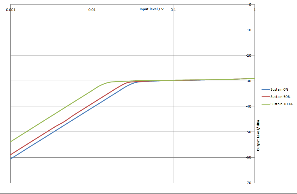
I also saw that say that THD was about 2% at 330mVRMS input, 5% at 560mVRMS and 10% at 1VRMS for all traces. This means that the main source of distortion was unrelated to the position of the sustain control. I imagine T5 is to blame here.
The second graph is a frequency response graph at the same three 3 sustain control positions. A 10mVRMS input signal was used for the uncompressed signal and a 100mVRMS for compressed signals. It can be seen that the frequency response in compression has an increase in bass frequencies, whereas the uncompressed response has a treble emphasis.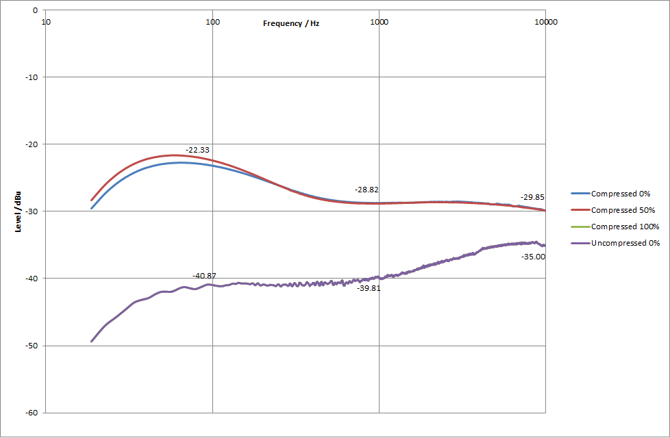
- The DC9 appears to fit point 1 for me, the compression ratio is better than 20:1
- With the sustain control at 100%, the range between compression onset and 2% THD is about 20mV to 330mV – about 24dB, which is pretty good.
- There’s about a 6dB bass hump at 100Hz in compression and a 5dB treble hump out of compression. This is not very flat!
- Point 4 could be addressed, but since lower voltage at the COMP BIAS results in the reduction in gain(compression), I can’t simply buffer the signal here and drive an LED. I’d use a comparator type circuit.
I probably won’t be using this for my IEM solution, but since it was only £8 on ebay, it’s not the end of the world! It will probably find its way onto my pedal board.
Test data is here:
Hope somebody finds this information useful! Bear in mind that Use it at your own risk and for your own enjoyment.