Mains voltage in the UK and the EU – and what it means for guitar amps.

Mains voltage in the UK and the EU

There seems to be some confusion about mains voltage in the UK: whether the UK is on 230VAC mains or 240VAC. The answer is both, kinda. We’re on 230VAC on paper and 240VAC in practice. It’s not a hugely interesting topic, but it has some implications for modern guitar amps in the UK. Although this article is written in July 2020 (the UK is currently in a transition period, having left the EU), there’s been no suggestion that we’ll move back to the 1980s 240VAC standard.

What happened to mains voltage in the UK and the EU?

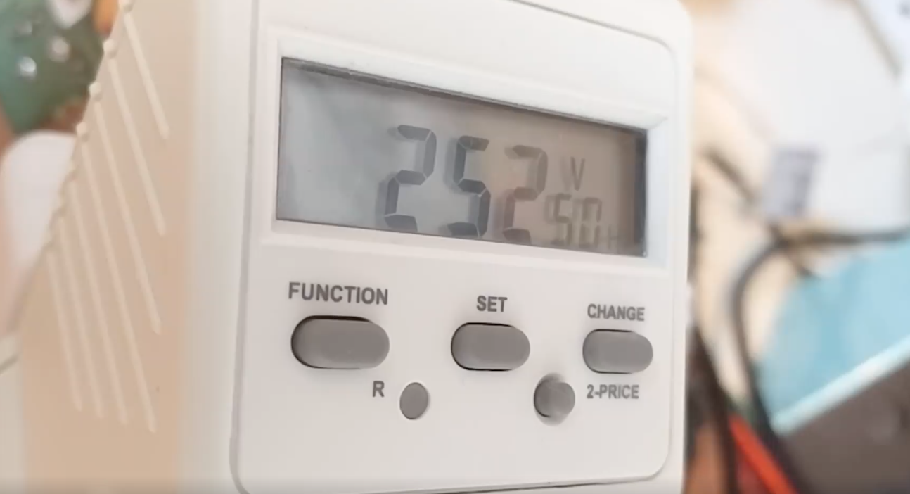
The UK has always had a nominal 240VAC power grid. Many European countries ran nominal 220VAC. It’s important to understand that these were only nominal voltages. The actual voltage coming out of the wall varied around the nominal voltages. The variance in most countries was around +/-6%. In 2003, mains voltages across the EU (which then included the UK) were standardised to 230VAC +/- 10%.

(Actually this is a slight over simplification. The harmonisation was staged through the 90s and 2000s and there are localised sublimits (-10%/+6%) for the voltage coming out of the wall, but the product harmonisation is for +/-10%).

At a similar time, Australia (the other economically ‘big’ 240V country) also standardised to 230VAC.

From the table below we can see that the new harmonised limits allowed every country to keep their wall voltages basically the same.

AreaRangeLower limit VrmsNominal VrmsUpper limit Vrms
Old UK 240V (1988)+/-6%226240254
Example 220V+/-6% (example)207220233
New EU+/-10%207230253
There’s no practical change to wall voltage. We’re still running 240VAC nominal through the grid, they’re still running 220VAC nominal. Everyone’s happy (except Nigel, of course).

See here, here and here for sources.

There’s no change to mains voltage at the grid, so what’s the point? Why did they do it?

Because it makes it easier for manufacturers. Rather than having to make and hold stock of nominal 220V and 240V equipment, the manufacturer only needs to hold stock of nominal 230V equipment. It’s then the manufacturer’s responsibility to make sure that their product works reliably between 207-253 volts.

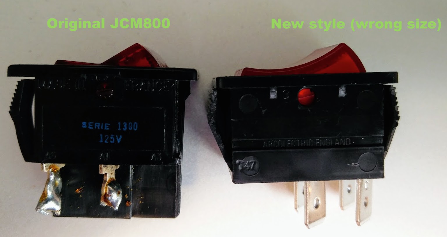
It also means that it’s not necessary to have a flimsy rotary switch (Silverface Fender) on the back of the amp that can easily be knocked into the wrong voltage as it’s being loaded in and out of the band van, or a dubious pull out voltage selector that allows access to hazardous voltages (JMI Vox), or an unreliable pull out voltage selector (plexi Marshall).

What does this mean for guitar amps and valve amps?

That depends on how savvy the manufacturer is. (I don’t want to generalise too much, but I’m afraid some of the North American manufacturers haven’t quite grasped the implications of this.)

The ‘wrong way’ to do it

As an example of what NOT to do, Fender now ship their ‘modern’ export valve amp products (OK, toob amp products) as 230VAC products. That’s fine. It’s better than those dodgy red switches on the back of Silverface amps.

In the UK, the amps see a 10% increase in mains voltages when the mains voltage is 253V. Taking the Blues Junior as example, this 10% increase increases the anode voltages and screen grid voltages on an already over biased EL84 until the valve burns out (often literally causes a fire). Not good.

This fire was caused by a design flaw in Fender Blues Juniors, which is exacerbated by Fender’s approach to the EU harmonised mains voltages. A new PCB was required.

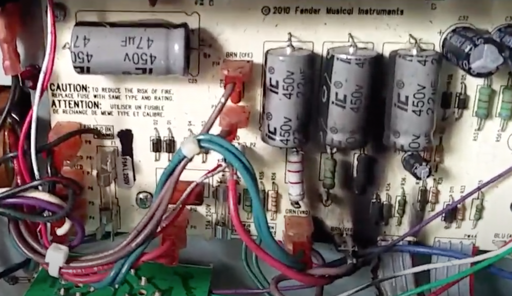
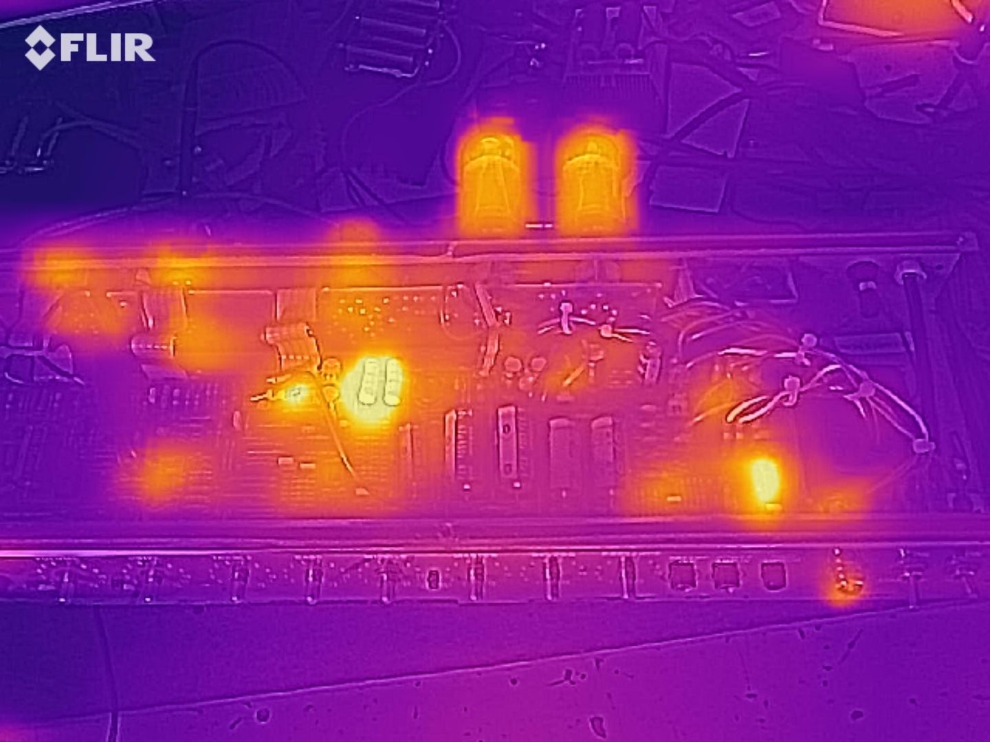
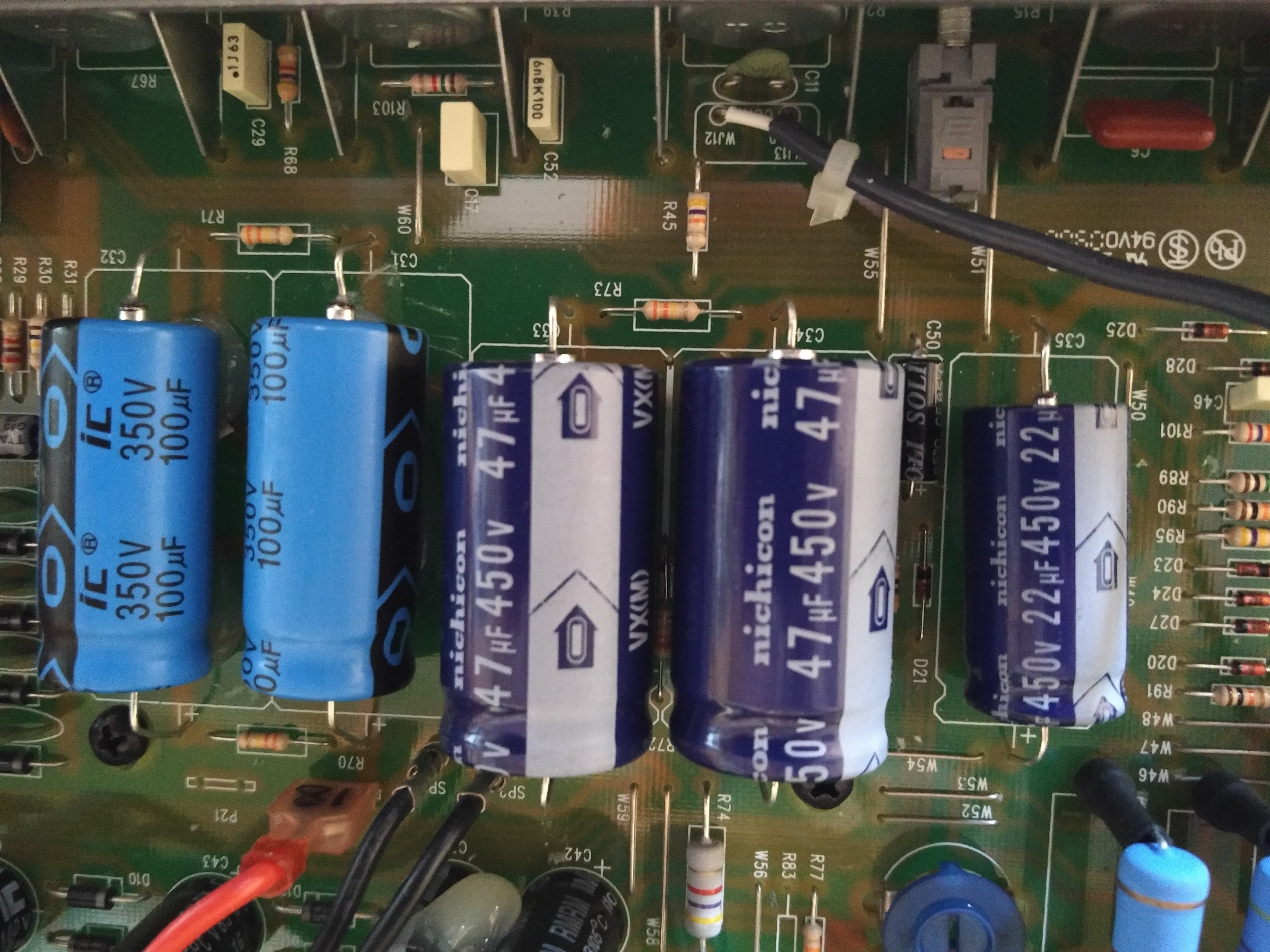
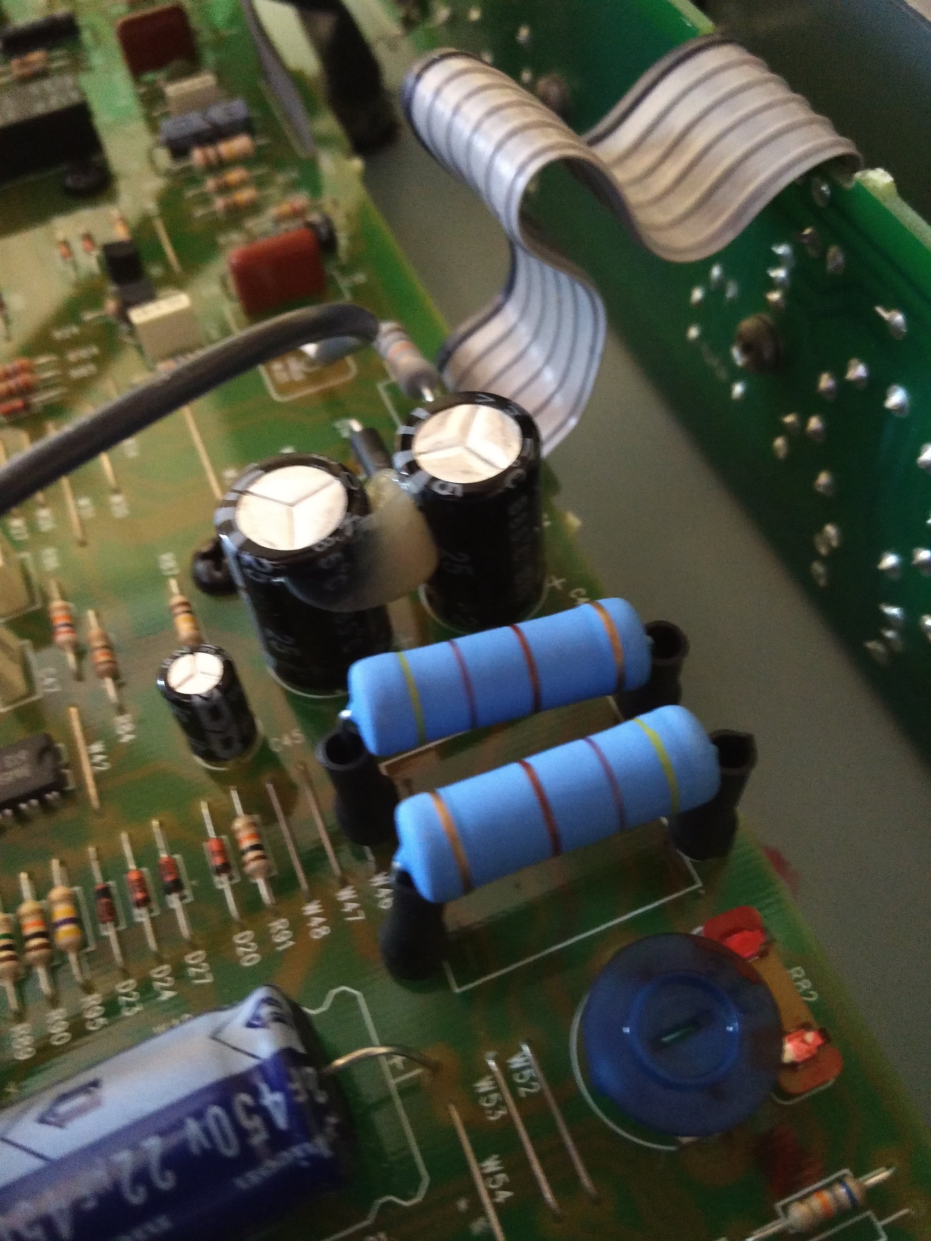
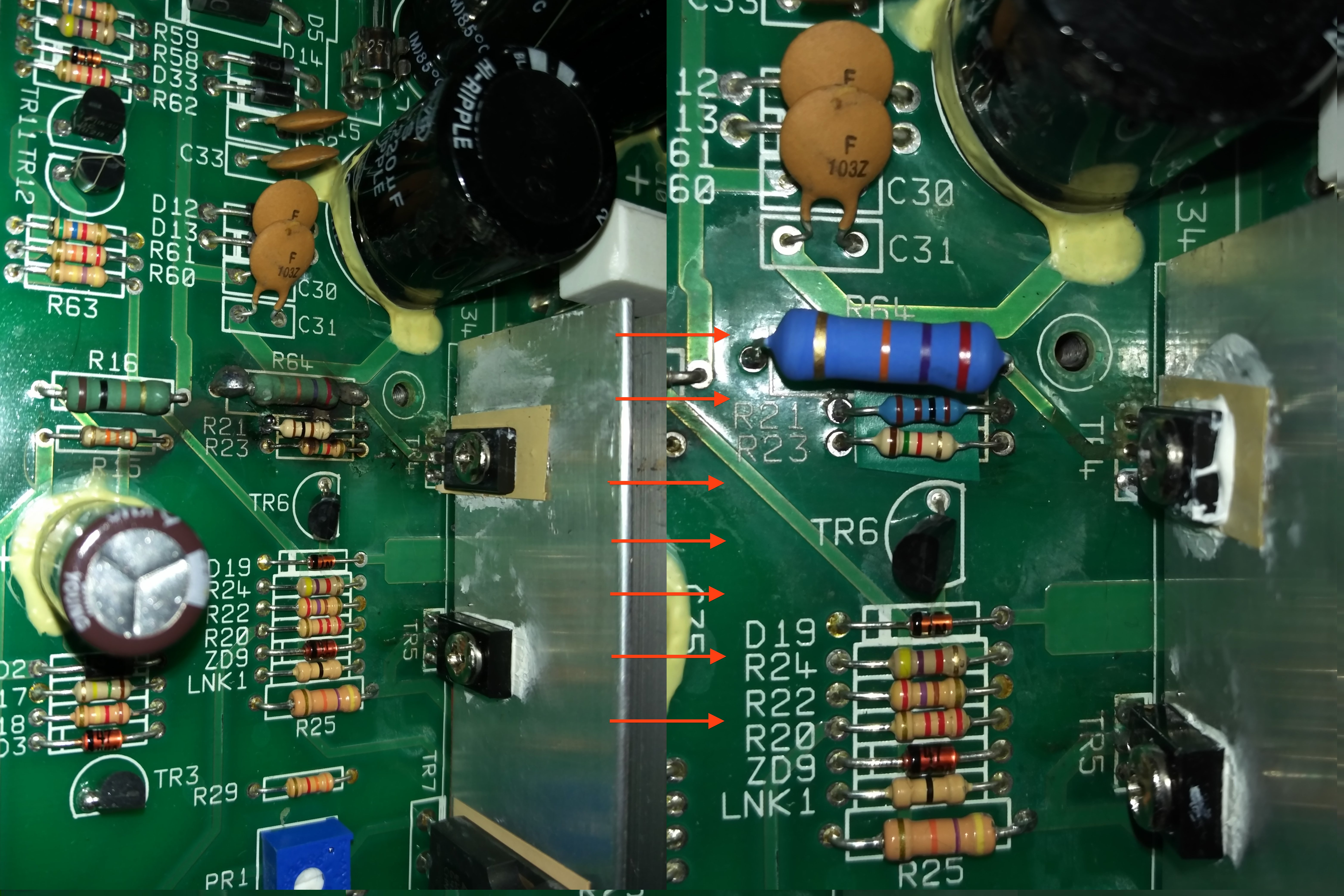
Taking the Hot Rod Deluxe as another example, the 10% increase causes the cheap electrolytic filter caps they use to be close to their rated limits leading to many filter cap failures. The mains increase also increases heat dissipation in the dropper resistors that they use for powering the FX loop and the reverb circuits leading to PCB damage in most UK Hot Rod Deluxes. Not good.

In a bizarre twist Fender have included a legacy 240V tap to the transformers on these products but they always wire to 230V. Fender have said ‘thanks very much’ to the single stocking EU models but ‘no thanks’ to putting in the minor R&D effort to make their amps reliable across the EU/UK/Australia on the 230V tap. A good UK/Aussie tech will always rewire a 230V Fender to be 240V for use in the UK. But clearly this shouldn’t be necessary, these are existing design issues that are compounded by the mains variation and they could be fixed so that the amps can always work across the 207-253VAC rage.

Just in case it’s not clear, this is not a problem with the standardisation, it’s a problem with the design.

The ‘right way’ to do it.

The sensible thing to do would be make sure that all amps will still be running under conditions that make them reliable at all extremes.

You don’t want an amp that drops out at 207VAC on a heavy load day in Germany and you don’t want an amp that burns up with 253VAC on a light load day in the UK. Ideally, the amp will run it’s rated power at 230V nominal and then the UK customers will get a slightly more headroom on their amp, whilst the EU customers will get something a tiny bit more crunchy. The manufacturer must run reliability tests on their units at 207VAC and at 253VAC.

If you want to know the difference in ‘tone’ that this will result in, then I’ve made a handy video below!

Valve amp filaments don’t like to be overpowered OR underpowered. By coincidence they’ll tolerate a +/-10% deviation from their 6.3V nominal. So if a manufacturer gets the 6.3V bang on at 230VAC, then the filaments will be happy anywhere in the EU.

To fix that Hot Rod Deluxe we’d increase the dissipation of the dropper resistors to allow for the amount of heat they’d have to dissipate at 253VAC and raise them away from the PCB and we’d use better filter caps or a series cap arrangement such as the one they use in the Hot Rod Deville. To fix the Blues Junior they should reduce the anode and screen grid voltages so they’re not going to burn out the valves and adjust the output transformer accordingly. If they have to reduce the rated output from 15W to 14W, who cares?

Is there an impact upon tone?

The million pound question… Yeah there’s a subtle impact. Here’s video with a Laney Lionheart running the 230V rated amp from 207VAC to 253VAC.

That is a 5W cathode biased Class A amp. Other amps will respond differently. It depending on the bias method, the screen grid resistors and tens of other things. Honestly, it’s one of the less significant things you can do. You’ll get more difference from changing string gauge, or moving your guitar volume a fraction, or a subtle boost pedal.

I’ve got a Fender amp in the UK, how can I change it to 240V?

I’m afraid this is one of those questions where if you have to ask, it’s not safe for you to try. These are lethal voltages and I’m not going to give any advice about doing this, either on this page or by email. My advice is to take it to a qualified amp repairer.

If you have a Fender amp in the UK, bring it to me (or another competent engineer) to get the transformer tap changed to 240V so it works better with mains voltage in the UK. Depending on the model, if the amp is brand new then this might be all that’s necessary for now, but if it’s a few years old then other work may be necessary to rectify issues with the amp.

Blackstar HT100 repair

Blackstar HT100 repair

This Blackstar HT100 repair was completed for the co owner of an exciting new Grantham based venture ‘Melody Music Rooms’ in Grantham.

Melody music rooms are a rehearsal space, recording facility and teaching space located on Westgate in Grantham . It’s the brainchild of a group of Lincolnshire and Nottinghamshire music teachers who wanted to provide better music services in the area. Not just a building, they run jam nights and busking sessions featuring local young (and old!) musicians. It’s great to have these guys raising the profile of live music in the area, so do check them out on https://www.facebook.com/melodymusicrooms/.

I’m told that this amp has played Wembley(!) as the owners of Melody Music played some high profile support gigs with their old band. It had been retired when it started blowing fuses, but the owner wanted it brought back to life for the new Melody venture.

There were a couple of valves to replace and the amp had blown the bridge rectifer diodes. Unfortunately Blackstar don’t provide schematics for their amps so it’s always a bit of a tough job repairing Blackstar gear.

Normally at this point I’d put a clip of my repair video, but here’s the repaired amp being used in the studio at Melody Music Rooms.

If you need a Blackstar HT100 repair, please drop me a line.

Fender Hod Rod Deluxe Repair

Because the Hot Rod Deluxe is the world’s most popular valve amp [citation needed], I get a Hot Rod Deluxe Repair arriving quite regularly.

The amp has two common faults, which are well documented:

The most common fault is the Low voltage power supply (LT supply) failure. This powers the opamp driven reverb and effects loop. Fender create their 16V low voltage power supply from a 33V and create significant heat in the dropping resistors and zener. This heat then causes the copper to delaminate from the PCB, leading to crackles and bangs and occasionally complete signal dropout. You can see the heat issues on this picture, taken with my thermal camera. The dropper resistors are getting hotter than the power valves! (Update 2020: repair kit available here): Hot Rod Deluxe Repair Thermal

On older hot rod deluxe repairs there’s some PCB retracking work to do to repair the PCB damage. On newer amps I can just take preventative action – replace the 5W dropper resistor with a 5W part raised off the PCB with ceramic spacers and replace the replace the zener also raised off the board.

The second common fault is the grey ‘IC’ (Illinois capacitor) electrolytic filter caps which are prone to failure. Fender use these presumably because they’re the cheapest 450V axial caps around. In fairness to Fender, there are probably hundreds of Hot Rod Deluxe amps using these caps that are still working, but there are also a lot that fail. I use a mix of quality F&T (German) and Nichicon (Japanese) capacitors to replace these parts and I recommend replacement on all Fenders when I’m already removing the board.Hot Rod Deluxe Repair Caps

I overrate all caps significantly The cost increase is only a few pounds but leads to better performance and improved lifespan. The most important caps are C33 My preferred configuration is:

C36 (overrated by 100V)
C35 (Overrated by 50V)
C33 (overrated by 470V using 2 series caps!)
C31 (overrated by 470V using 2 series caps!)

Update Sept 2020: At the time of this post (2018), great quality Nichicon and F&T axial caps were still available. 2 years later, Axial caps are going the way of the dodo so I’ve switched to using high reliability radial RubyCons with a special adapter board  (which I’ve made available to others as a repair kit available here).

The other thermal ‘weak point’ is the footswitch circuit, which gets the same treatment as the other hot resistors in the LT supply.

If you need a Hot Rod Deluxe Repair, please contact me.

Hot Rod Deluxe repair Dropper resistorsHot Rod Deluxe Repair ZenerHot Rod Deluxe Repair Footswitch Dropper

Peavey Classic 30 repair –

Peavey Classic 30 repair

This Peavey Classic 30 repair was a bit of a nightmare!

It arrived with a fairly basic problem – the amp wouldn’t turn on. This was down to a loose screw. It held the mains fuse holder internally. When this came loose, the fuse holder was dangling in mid air and shorted mains directly to the metal case of the unit, which caused the fuse to blow – which is a good thing!

I spent an hour on it – tested all the valves and checked the plate and other power supply chain elements – all the preamp valves are good, but the inner power amp valves no longer match so I changed these. There was no means of adjusting the bias so it’s a question of juggling valves until I find a set of EL84s that properly bias.

I then soak tested the amp. This involves running the amp at gigging voltages with a pink noise signal for a couple of hours. I do this to check that there aren’t any problems with the amp that only appear after a longer period.

In this case, the amp started making a crackling noise after the two hour soak. This turned out to have a twofold cause – there was a leaking cap in the tone stack and the HT electrolytics (IC brand) were also worn.

Unfortunately the design of these early peavey Classic 30 amps uses single wire links between the boards. It’s a nightmare to disassemble and these little wire links are a common cause of failure. This slowed down the diagnostic quite severely

If you need a peavey classic 30 repair, please do contact me.

Blackstar Series One repair S1-104EL34

Blackstar Series One repair

This Blackstar Series One repair from February was a bit of a mess! The amp had unfortunately received the unhelpful care of another repairer who had left the amp in a terrible state. If you don’t like to see damaged PCBs, look away now.

It was brought to me because it was blowing fuses at gigging levels. The owner had bought it second hand and it had started blowing fuses recently. A quick fix was managed in time for a gig!

I’m not sure what the original fault was with this amp, but whoever had previously attempted to fix it was very much of the ‘add more solder’ school of repairing! I suspect that they had not attempted to remove the board and had just tried to repair the amp from the top side only in doing so they’d damaged to PCB and left the transistor hanging by a thread of pad..

Blackstar Series One repair3You can see the horrible original work on the left and my improved fix on the right of the image. I removed the board and cut away the damaged track and recreated a solid connection with solid core wire on the board reverse. I replaced the burnt out components nearby with suitably rated high power resistors. I also replaced the transistor.

The whole job took 3 hours and included a valve test (revealing three worn preamp valves) and an additional (FOC) 1 hour soak test at gigging levels.

If you have a blackstar series one repair, please drop me a line.

Here’s a video of the amp, once fixed.

Fender Brownface repair – Super Amp 6G4A

This Fender Brownface repair was something of a labour of love here at Keld Ampworks. It’s a fascinating amp – having started life presumably in America, it’s got a 110V transformer. At some point it made its way to Belgium, where it was ‘converted’ to EU voltages, using a rather scary transformer bolted to the inside of the woodwork. It was later bought by the current owner and brought to the UK.

This was my first Fender Brownface repair. I’ve done blackface Fenders, Tweeds and Silverface fenders but never before a Brownface. Nice to have something new.

My first task was to make the amp safe. The Fender ‘death cap’ is well documented elsewhere so I won’t dwell on it. Suffice to say that it was removed, and a 3 core earthed mains lead with US plug fitted. The fuse and mains power switch were moved to the ‘live’ line. They don’t make ’em like this any more! The scary open frame in-cabinet transformer was also removed from circuit and replaced with a removable US-UK transformer. This makes the amp more ‘original’ and also safer. Double win!

Most of the preamp tubes were still good. The power valves were replaced with a new set of Sovtek 5881s and one preamp was replaced. The valve sockets were all tensioned and cleaned.

Checking the filter caps inside I saw that 2 out of 7 had already been replaced – but with underrated parts (350V instead of 500V!). Of the remaining five, three were leaking electrolyte and so after consulting the customer I replaced all 7. I was able to preserve the original filter cap covers and use them to conceal modern Rubycon parts at 700V.

At this point the amp was much more stable but had a few intermittent crackles and bangs. Many of these were sorted by replacing some coupling capacitors.

The last issues were with the ‘Vibrato’ channel. The vibrato modulation was bleeding through horribly onto the normal audio signal. This turned out to be further cathode bias and coupling issues.

If you need a fender Brownface repair, please give me a call.

Blackstar HT5 Repair, Keld Ampworks, Newark, near Stamford

Blackstar HT-5 repair

I’ll admit this Blackstar HT5 repair had me confused for a bit. It was brought to me from Stamford Endowed School, which isn’t that far away from my workshop in Newark, it is just down the A1.

The amp arrived with no sound output from the speakers. The valves tested fine, one 12ax7 and one 12bh7.

Looking inside the amp I could see signal on both grids of the 12ax7, but nothing was getting through to the output stage.

Using a thermocouple I tested the temperature of the semiconductors in the amp and found that the two MOSFETs were getting rather hot!

Upon inspection, I saw that somebody had drilled two little holes between the MOSFET legs and left all the swarf (mangled metal pad and PCB resin).

It turns out that there’s a forum post saying that the MOSFET pads were apparently quite close together and prone to arcing. I think that somebody read that post and decided to go DIY on this amp, not understanding that leaving chewed up pad around the holes would gonna cause a worse problem than arcing. 🙁 It probably worked for a bit but it worketh no longer.

https://www.blackstaramps.com/forum/viewtopic.php?f=32&t=2135&sid=2959070778299b62b9ca529437626388&start=10

After replacing the burnt out drain resistors and the damaged FETs, the amp was back up and running. These are really great little amps and put out a lot of volume, despite their 5W rating.

If you need a Blackstar HT5 repair, please contact me.

Bogner Repair – Shiva MK II

Bogner Repair - Shiva

This Bogner repair was sent over all the way from Liverpool on the recommendation of a Liverpool tech who makes fantastic boutique point to point gear, but doesn’t deal much in modern technology.

The issue was with the DC heater supply which uses a switch mode power supply. Mr Bogner decided to use a switch mode to reduce weight in the amplifier.

The first stage was to verify that the amp worked with an external power supply: here’s a video of the first tests.

The Liverpool tech had already done some work on the output stage. My work on the SMPS was completed fairly quickly and it’s waiting to head back on the 100+ mile trip to Liverpool.

The owner was happy! 🙂

If you need a Bogner repair, please get in touch

Hughes and Kettner Grandmeister repair

Hughes and Kettner Grandmeister repair

I’ve been hoping for a Hughes and Kettner Grandmeister repair since they first came out. Luckily for me when the amp’s owner saw my tubemeister repair blog he decided to send his amp all the way from Kent to be repaired at my Newark workshop. Apparently his local amp tech said ‘I don’t do modern amps!’ 🙁

He missed out on a really interesting job – Hughes and Kettner have invented a ‘TSC’ Tube safety control auto biasing circuit that monitors the tube bias and shuts off the tubes if they get out of spec. Unfortunately a faulty tube had taken out the tube safety control – oops! I replaced the circuits with these 4 TSC MOSFET s to finish the job – see picture below.

It’s a tightly packed amplifier with not much space so it took a bit of work to get in there and repair the TSC circuit but it wasn’t too bad a job. Here’s a video of the completed job.

The one disadvantage with Hughes and Kettner amps is that they tend to show up fingerprints, so I gave the amp a good wipe down before posting it back to Kent!

If you need a Hughes and Kettner Grandmeister repair, please feel free to bring it or post it to me.

Hughes and Kettner Grandmeister repair - resistor mounting

Hughes and Kettner Grandmeister repair - midi board

Hughes and Kettner Grandmeister repair - TSC repair

Hughes and Kettner Grandmeister repair - power off circuit

Hughes and Kettner Grandmeister repair

Hughes and Kettner Grandmeister repair - cleaning

Hughes and Kettner Grandmeister repair

Hughes and Kettner Grandmeister repair

Marshall 2554 JCM 800 combo repair

Marshall 2554 JCM 800 combo repair-4

This JCM800 combo repair came to me for a full service before the user sold it. It also had a common problem with the power light illumination.

I spotted a few things during the service. A bit of preventative action has hopefully made the amp a more pleasurable experience for the user.
Replacement Marshall JCM800 Switch
There were a couple of dry joints around the potentiometers. All three preamp valves failed test.

The valve socket for the preamp valve was damaged and required replacement – I used a new Belton PT range socket, I find these to be durable and high quality with a good solid fixing. The first valve socket was

The illumination switch would have been a nice simple job, except that the part sold by Hot Rox as a “Marshall JCM800 power switch” was too wide for the chassis slot. Fortunately I found a suitable replacement from RS. That’s one to beware of in future!

The owner was good enough to write me a nice review of the service. 🙂

Replacing power switch Marshall 2554 JCM800 combo repair-1
If you need a JCM800 Combo repair please get in touch and I’ll get it sorted for you.